Hummer H1 (2002+). Manual — part 189
_____________________
Heating/Ventilation/Air Conditioning (HVAC) 11-35
®
05745159
BLOWER MOTOR RESISTOR REPLACEMENT
Removal
1.
Remove HVAC harness connector from resistor
(Figure 11-50).
2.
Remove screws and resistor from cowl.
Installation
1.
Fasten resistor to cowl with screws.
2.
Plug HVAC harness connector into resistor.
3.
Check blower motor operation.
Figure 11-50: Blower Motor Resistor Replacement
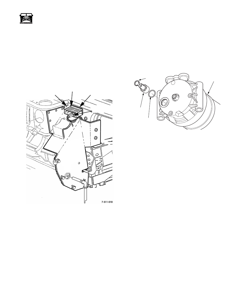
HIGH PRESSURE CUTOFF SWITCH
The high pressure cutoff switch is located in the rear of the
compressor. The switch is wired in series with the compressor
clutch and exposed to high side pressure in the compressor.
Should pressure exceed the switch setting, current will be in-
terrupted to the compressor clutch until the pressures drop to
safe levels, then the switch will close allowing the clutch to en-
gage (Figure 11-51).
Figure 11-51: High Pressure Cutoff Switch
COWL
SCREWS
RESISTOR
HVAC HARNESS
CONNECTOR
7-S11-054
SNAP RING
HP
SWITCH
ORING
COMPRESSOR
(REAR VIEW)

11-36
Heating/Ventilation/Air Conditioning (HVAC)
______________________
®
HVAC CONTROLS
Figure 11-52: HVAC Control Panel
The HVAC system is operated using a control panel. The panel
has controls for:
• Blower speed
• Air temperature
• Mode
• Air conditioning
• Rear window defrost (Optional)
Status for all of the controls is shown using painted marks on
the faceplate of the control panel. Operation is based on driver
input, no automatic function is incorporated. Controls for the
HVAC system are based on (vacuum) door motors and water
valve controls, and (electric) blower motor and temperature
door motor controls (Figure 11-52).
Blower Speed Dial
The blower speed dial has 4 positions.
• Low
• Med 1
• Med 2
• High
The operator selects the fan speed by rotating the dial clock-
wise (Figure 11-53).
Figure 11-53: Blower Speed Dial
Temperature Dial
The temperature dial controls the temperature of the air exiting
the HVAC unit. When the dial is rotated to the cold position,
the water valve is shut off and the temperature door isolates the
heater core. When the dial is rotated to the HOT position, the
water valve opens and the temperature blend door directs air
through the heater core. Between COLD and HOT, tempera-
ture is regulated by changing the amount of air that passes
through the heater core (Figure 11-54).
Figure 11-54: Temperature Control Dial
Mode Dial
The mode dial allows the operator to direct air to a selected
area. When the driver rotates the dial clockwise and chooses a
mode, vacuum is sent to the vacuum motors that must close
(Figure 11-55).
NOTE: When the main HVAC unit is without vacuum, air will
be directed to the defrost and floor vents, and fresh air will be
used. The blower motor on the HVAC unit will not function if
the mode dial is set at the OFF position. When the dial is posi-
tioned on an A/C position, the compressor clutch will be acti-
vated.
Figure 11-55: Mode Dial
7-S11-073
REAR DEFROST (OPTIONAL)
HVAC CONTROL HEAD
7-S11-073
7-S11-073
7-S11-073
7-S11-073
_____________________
Heating/Ventilation/Air Conditioning (HVAC) 11-37
®
05745159
UNIT SERVICE
WARNING: When working with refrigerant, always
use protective equipment to prevent injury. Refrigerant
handling should be done only by technicians trained
and certified in the use of refrigerant and refrigerant
service equipment.
CAUTION: Use only equipment and materials designed to op-
erate with R134a refrigerant. Never substitute parts or materi-
als designed for R12.
CAUTION: Never use sealers in or on the HVAC unit that are
not designed for ventilation systems. Some sealers release nox-
ious or irritating odors that will be offensive to operators of the
vehicle. Neutral cure sealers should be used when sealing any
area of the HVAC unit that could potentially expose the opera-
tor of the vehicle or the passengers to the released chemicals.
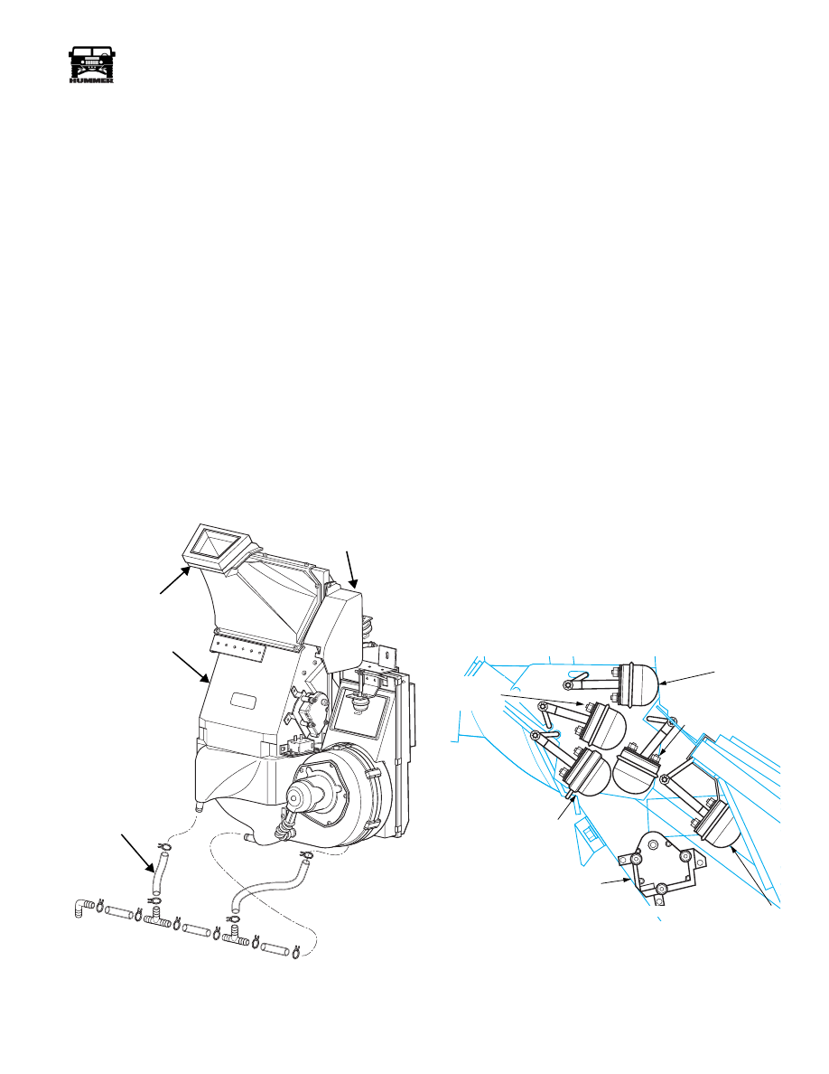
MAIN HVAC UNIT
The main HVAC unit is comprised of a heater core for heating
air, and evaporator for cooling air, mode doors to direct air-
flow, and an electric blower motor and fan to force air through
the case to be heated or cooled, then directed to the selected
zones in the vehicle (Figure 11-56).
Figure 11-56: Main HVAC Unit
Diverter Doors
Four diverter doors occupy the outlet area of the main unit.
Various positions and combinations of 4 doors provide the sys-
tem with the following mode selections:
• Off
• Maximum A/C - Recirculate
• A/C
• A/C Face/Floor blend
• Face
• Floor
• Defrost/Floor blend
• Defrost
All 5 of the mode doors are operated using vacuum door mo-
tors mounted externally to the case (Figure 11-57). The motors
are as follows:
• Floor door motor
• Defrost blockoff motor
• Face door motor
• Defrost door motor
• Recirculate door motor
The vacuum motors are capable of 2 positions: fully extended
(spring pressure), or fully retracted (vacuum). The face door
motor is an exception, having a third position in the middle of
travel. A second vacuum inlet is added to the face door motor
for this purpose (Figure 11-57).
The temperature blend door motor operates the temperature
blend door. This door is responsible for regulating outlet air
temperature by directing air through the heater core or by
blocking air to the core. The temperature blend door motor is
electric, and can be positioned at multiple positions.
Figure 11-57: Vacuum Door Motors
7-P11-001
7-P11-001.4
VACUUM MOTOR
FACE OUTLET
DRAIN TUBE
COVER
MAIN HVAC UNIT
7-S11-031
TEMPERATURE BLEND DOOR
FACE DOOR MOTOR
DEFROST DOOR
MOTOR
FLOOR DOOR MOTOR
RECIRCULATE DOOR MOTOR
DEFROST
BLOCKOFF
MOTOR
11-38
Heating/Ventilation/Air Conditioning (HVAC)
______________________
®
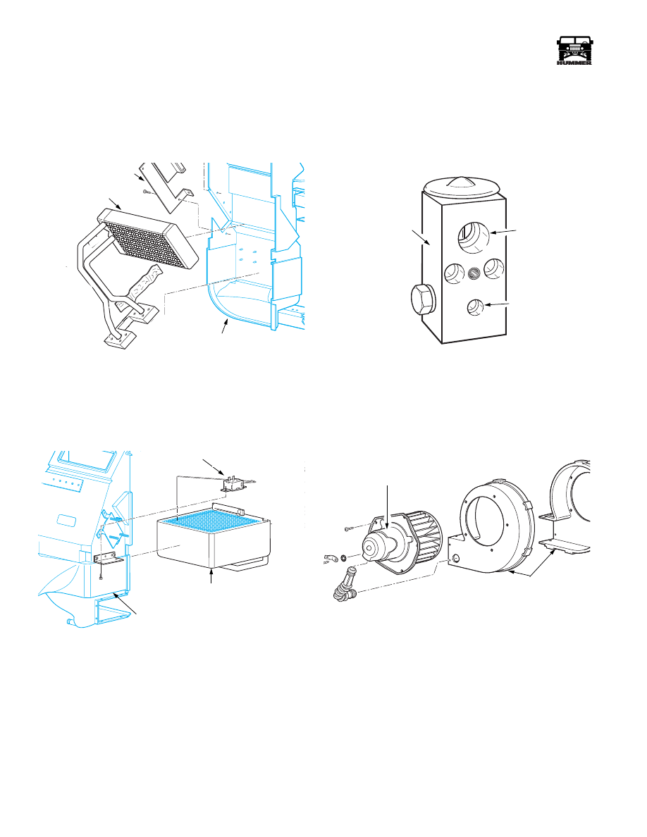
Heater Core
The heater core is composed of copper and brass with numer-
ous passages allowing heated engine coolant to pass through,
transferring heat into the passing air from the blower motor.
Coolant flow through the heater core is controlled by the water
control valve in the engine compartment (Figure 11-58).
Figure 11-58: Heater Core
Evaporator
The evaporator is composed of a wide flat aluminum tube bent
in a serpentine pattern. Fins extending out from the tube assist
in transferring heat from the passing air into the refrigerant
which is evaporating inside of the tubes (Figure 11-59).
Figure 11-59: Evaporator
Thermostatic Cycling Switch
The thermostatic cycling switch is mounted on the side of the
main HVAC unit (Figure 11-59). The thermostatic cycling
switch is responsible for turning off the compressor clutch
when evaporator temperature approaches freezing. Tempera-
ture is sensed by a capillary tube inserted in the fins of the
evaporator. Should the evaporator reach freezing temperatures,
moisture condensing on the fins of the evaporator will freeze
and hinder air flow. The thermostatic cycling switch will inter-
rupt current to the compressor clutch until the temperature rises
to about 40° F.
Expansion Valve
The expansion valve controls the flow of refrigerant through
the evaporator. Refrigerant must be metered to prevent the liq-
uid refrigerant from flooding the evaporator. The expansion
valve is exposed to both low and high pressures, and bases re-
frigerant flow on the pressure which is exiting the evaporator
(Figure 11-60).
Figure 11-60: Expansion Valve
Blower Motor
The blower motor is a permanent magnet electric motor that
drives a wheel type fan. The air enters the unit from the outside
air intake, or from a door on the interior of the vehicle. The air
is then forced through the evaporator and heater core.
Figure 11-61: Blower Motor and Housing
Rear Defrost Button
The vehicle may be equipped with optional rear defrost. The
rear defrost is comprised of an electrical grid which is bonded
to the rear center glass. When the rear defrost button is pushed,
a timed electric current is sent to the grid causing the tempera-
ture of the grid and glass to slowly rise, melting frost or evapo-
rating exterior window fogging. The timer in the switch will
shut off the current when an adequate amount of time has
passed. This option is only available on the XLC2, and HMC4.
HEATER CORE
RETAINING BRACKET
HVAC CASE HALF (FRONT)
7-P11-004
EVAPORATOR
HVAC CASE HALF (REAR)
THERMOSTATIC
CYCLING
SWITCH
7-P11-004
7-S11-061
INLET
OUTLET
EXPANSION VALVE
BLOWER MOTOR
BLOWER HOUSING
7-P11-003.1
Нет комментариевНе стесняйтесь поделиться с нами вашим ценным мнением.
Текст