Hummer H1 (2002+). Manual — part 190
_____________________
Heating/Ventilation/Air Conditioning (HVAC) 11-39
®
05745159
MAIN UNIT REPLACEMENT
Removal
1.
Drain Coolant into an approved container.
2.
Recover refrigerant.
3.
Remove raincap and adapter.
4.
Remove air intake elbow, air cleaner and splash shield.
5.
Remove 4 bolts securing heater core extension tubes. Plug
all open holes and discard all sealing washers
(Figure 11-62).
Figure 11-62: Heater Core Extension Tube Removal
6.
Remove any pliable sealer from exterior of the
passthrough plate.
7.
Remove the center console.
8.
Remove the right side crash pad.
9.
Remove the fastener from passenger side closeout panel.
10. Lower panel down to gain access to the floor outlet hose,
remove the screw securing the hose, and remove the
closeout panel.
11. Remove 2 screws securing the passenger side of auxiliary
heat/cool unit. Raise the cover up approximately 2" and
support with a block of wood. Remove the passenger side
door strap bracket and seat belt.
12. Remove the front passenger seat, and the right front inner
and outer kick panels.
NOTE: Panels are removed to prevent damage that would oc-
cur during HVAC unit removal.
13. Note HVAC harness positioning prior to removal/
disconnect.
14. Disconnect the vacuum motor harness, engine HVAC
harness, water valve harness, temperature blend door
connector, cycling switch connections, power mirror
harness, resistor harness, power door lock harness, power
window harness and blower motor connections
(Figure 11-63).
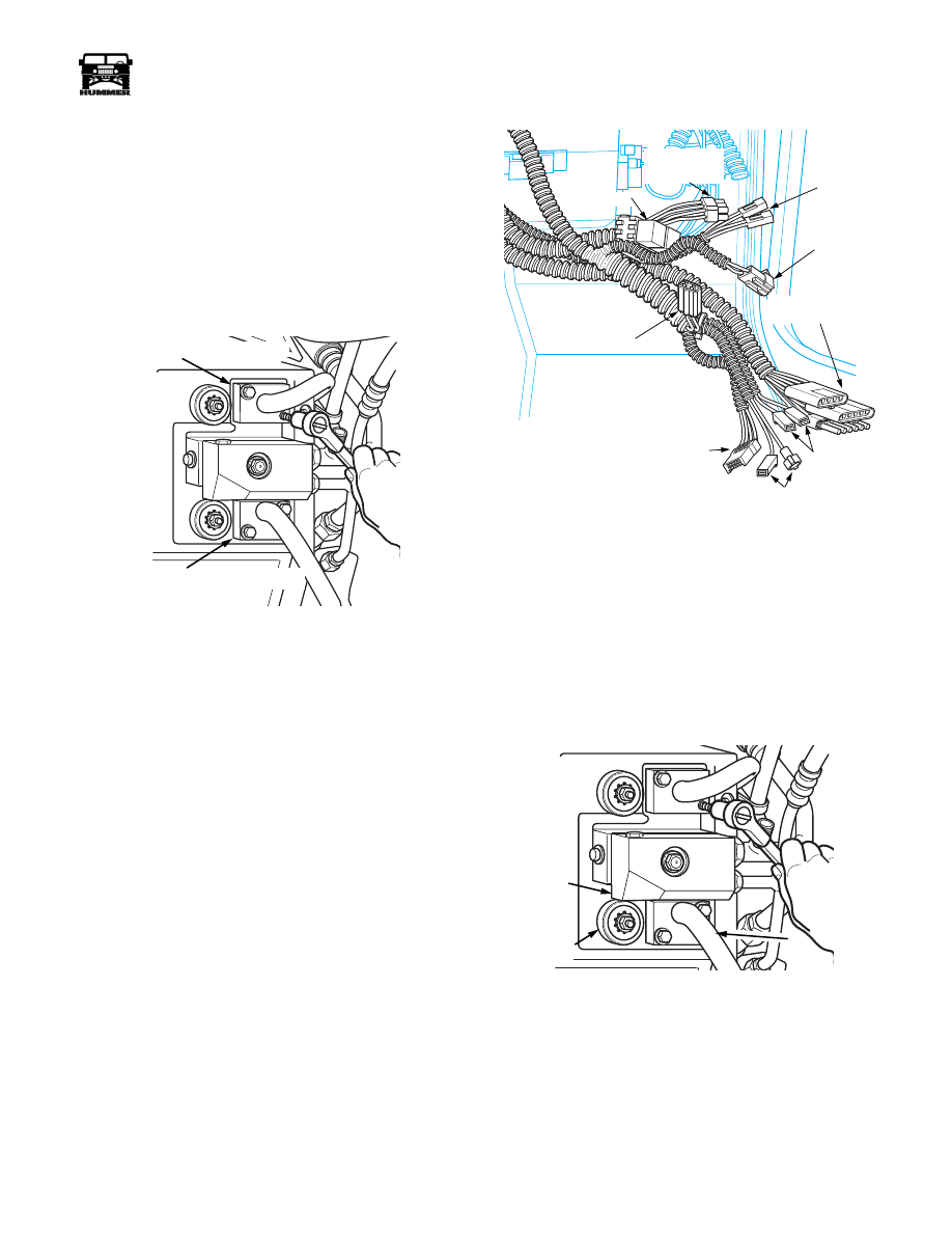
Figure 11-63: Harness/Connector Identification
15. Pull harnesses clear of HVAC unit and secure.
16. Remove screw(s) securing the floor duct to the top of the
HVAC unit. Disconnect the hose going to the passenger
floor area and remove hose.
17. Remove bolt securing HVAC manifold block to expansion
valve and discard sealing gasket. Cap all openings
(Figure 11-64).
18. Remove 2 nuts, washers, and grommets from passthrough
mounts (Figure 11-64).
Figure 11-64: Passthrough Fastener Removal
19. Remove interior bolt securing left and right side of the
HVAC unit to the body. Support the unit prior to removing
the second fastener to prevent the unit from falling down
and causing possible damage or injury (Figure 11-65).
20. Removal of the unit can be accomplished by lowering and
pulling straight rearward.
00-S11-005
HEATER CORE EXTENSION TUBE
HEATER CORE EXTENSION TUBE
POWER MIRROR
ENGINE HVAC
VACUUM
CONTROL
RELAYS
RESISTOR
TEMP BLEND
DOOR MOTOR
BLOWER MOTOR
CYCLING
SWITCH
POWER LOCKS
AND WINDOWS
7-S11-062
MANIFOLD
BLOCK
PASS
THROUGH
MOUNT
HEATER CORE
EXTENSION TUBE
11-40
Heating/Ventilation/Air Conditioning (HVAC)
______________________
®
Installation
Lift HVAC unit into the vehicle.
1.
Set the lower bracket on HVAC unit on top of the lower
body bracket. Ensure that the studs on the pass through
plate align with the holes in the body. Harnesses must be
positioned to exit to the right side of the HVAC unit.
2.
Pivot the unit upwards until it rests against the defrost and
floor ducts. Install the right side fastener, and two nuts,
washers, and grommets on the passthrough plate. Slowly
tighten the front pass through mounts first. This action will
pull the unit forward. Ensure that the defrost and heating
ducts align properly with the outlets on the HVAC unit
before tightening inside mounts.
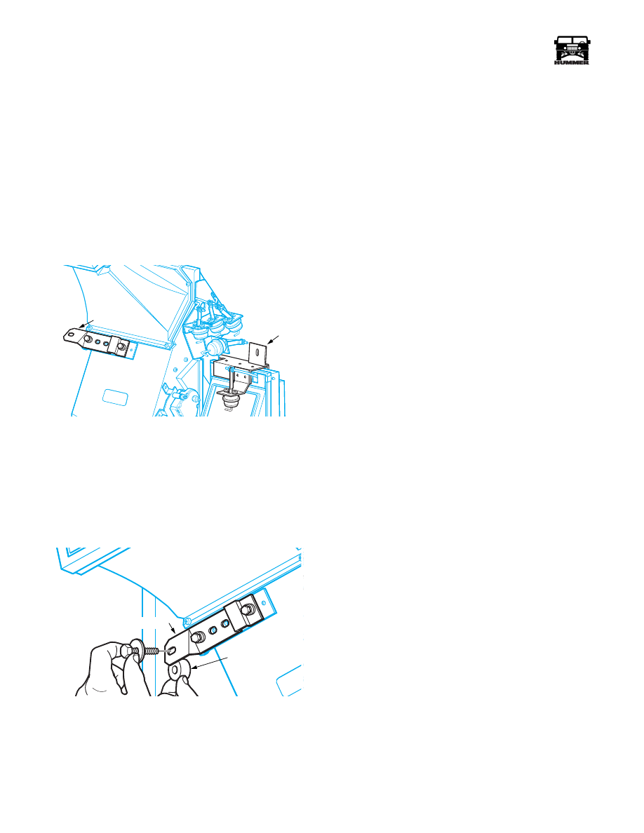
Figure 11-65: Interior mounting points
NOTE: The HVAC unit should have a 1/2” inch spacer be-
tween the left side bracket and the body. If the spacer was not
present when the unit was removed, it should be installed when
the unit is taken out of the vehicle for service.
3.
Install left hand interior fastener with the 1/2”spacer, it
may be necessary to loosen the bracket and slide it left or
right to align the hole. Tighten fastener (Figure 11-66).
Figure 11-66: Left Side Mount and Spacer
4.
Install screw(s) securing drivers floor duct to the main
HVAC unit.
5.
Install passenger side floor duct and route to the right as
previously removed.
CAUTION: Be sure to remove all of the devices used to plug
the openings in the heater lines and the A/C lines.
6.
Install manifold block to expansion valve using a new
sealing gasket, torque the fastener to 25 lb ft.
7.
Install heater core extension tubes onto passthrough plate
using new sealing washers. Torque the fasteners to 32 in lbs.
8.
Evacuate A/C system for 45 minutes, with 10 minute hold
time for leak check.
9.
Refill the cooling system.
NOTE: When refilling, use bleeder screws on engine and radi-
ator to purge as much air as possible from the system. The
bleeder screws also allow easier filling of the cooling system.
10. Recharge A/C system to 3lbs 2oz. Add 2oz. oil if the unit
is new or evaporator was replaced.
11. Leak check passthrough plate for body leaks using a water
hose. If leakage is noted inside vehicle, seal the leaks from
the outside using body sealer in small amounts.
12. Leak check the A/C lines using a R134a leak detector.
13. If no leaks are found, install air cleaner housing, elbow,
adapter raincap and air cleaner splash shield.
14. Connect vacuum control harness, cycling switch con-
nections, power mirror harness, door lock harness, power
window harness, blower motor connections, resistor
harness, engine HVAC harness, temperature blend door
connector, and water valve harness.
15. Install center console and check operation of A/C and heat.
16. If A/C and heat are functioning properly, install left front
and right front passenger side kick panels
17. Install right front seat and crash pad.
18. Install the right side closeout panel.
LEFT SIDE
MOUNT
RIGHT SIDE
MOUNT
7-S11-058
1/2” SPACER
LEFT SIDE HVAC UNIT MOUNT
7-S11-067

_____________________
Heating/Ventilation/Air Conditioning (HVAC) 11-41
®
05745159
VACUUM DOOR MOTOR
Replacement
1.
Remove right front crash pad.
2.
Locate and remove 2 screws securing vacuum motor cover
to main HVAC unit.
3.
Locate faulty vacuum motor and remove vacuum line. If
multiple motors are to be replaced, tag vacuum lines as
they are removed.
4.
Note position of mounting studs on the motor to be
replaced. Mark holes that studs pass through
(Figure 11-67).
Figure 11-67: Vacuum Door Motor Replacement
5.
Note position of motor arm relative to door lever. Mark
the side facing away from the HVAC unit.
6.
Remove the push clip with side cutting pliers and discard.
7.
Remove washer under push clip, do not discard.
8.
Remove two mounting nuts and vacuum motor
(Figure 11-67).
Installation
Reverse removal procedure
REFERENCE MARK
7-S11-039

11-42
Heating/Ventilation/Air Conditioning (HVAC)
______________________
®
BLEND DOOR MOTOR
Replacement
1.
Disconnect motor electrical connection.
2.
Remove 3 nuts securing motor to bracket (Figure 11-68).
Figure 11-68: Temperature Blend Door Motor
Removal
NOTE: Do not loosen set screw on door shaft adapter!
3.
Remove motor by pulling it straight off. Do not discard the
spacers behind the motor.
Installation
Reverse above removal procedure for installation.
Heater Core Replacement
NOTE: Screws should be noted for length as they are removed
to aid in correct reassembly. Some screw lengths are critical to
prevent interference with interior parts.
NOTE: Most of the screws used are threaded into the plastic
housing of the HVAC unit. Care should be used to prevent
over-tightening of the hardware and stripping holes out.
1.
Remove the unit from vehicle (Refer to unit removal pro-
cedure this section)
2.
Set the HVAC unit on a bench so the copper heater tubes
are visible and upwards.
3.
Remove permagum tape from heater tubes at passthrough
plate and discard.
NOTE: Foam tape and permagum tape should always be re-
placed with new material where it was removed from during
disassembly. The tapes are used to insulate hot and cold parts
and prevent condensation from dripping on the passenger
floor.
4.
Remove 4 bolts securing heater tube mounts to
passthrough plate (Figure 11-69).
Figure 11-69: Heater Core Tube Removal
5.
Cut sealer around heater core retaining plates (Figure 11-70).
6.
Remove 2 retaining plates (Figure 11-70).
Figure 11-70: Retaining Bracket Removal
7.
Pry heater tube mounting plate away from passthrough
plate. Pry only in the middle to prevent damaging seal
surfaces. Heater tubes extend past the mounting plate and
into the passthrough plate (Figure 11-71).
Figure 11-71: Removing Heater Core
8.
Pull lightly on heater core to keep heater tubes parallel
with the HVAC case. Do not allow the mounting plate end
to come away faster than the core. Note positioning of any
foam tape on the heater core, and duplicate on new part.
9.
Discard the sealing washers on the heater tubes and repair
or replace heater core as necessary.
Reverse removal for installation.
NOTE: Observe screws as they are removed to ensure corrects
screws are used in the correct location on assembly.
ORG
TEMPERATURE BLEND
DOOR MOTOR
NUT
SPACER
DOOR SHAFT ADAPTER
MOUNTING PLATE
7-P11-002
HEATER CORE
EXTENSION TUBES
7-S11-032
HEATER CORE
RETAINING PLATES
SEALER
7-S11-034
7-S11-035
Нет комментариевНе стесняйтесь поделиться с нами вашим ценным мнением.
Текст