Hummer H1 (2002+). Manual — part 222

_____________________________________________________
Electrical System 12-113
®
05745159
Cargo Door Lock Inoperative
Step
Action
Value(s)
Yes
No
1
Does power the lock system on vehicle operate
correctly?
Go to step 2.
Refer to the
diagnostic charts
that apply.
2
Open the primary cargo door. Using a DVOM
measure the voltage across the brass door contacts
on the body. Operate the door locks in both
“Lock” and “Unlock”. Does the voltage pulse
+12v then –12v?
+12v then –12v
Go to step 3.
Go to step 4.
3
Remove inner door panel and disconnect door
lock actuator. Using a DVOM set to measure
resistance, measure continuity between the door
contacts and door lock actuator on CKTS 117 and
121. Does the resistance meet the specification?
<.2
Ω
Replace the door
lock actuator.
Locate the open
or bad connection
in CKT 117 or
121.
4
Gain access to cargo door lock delay module. Dis-
connect the module connector. Using a DVOM set
to measure voltage, probe pins 9 (CKT 517), and 3
(CKT 59). Is the specified voltage present?
12v
Go to step 6.
Go to step 5.
5
Check the voltage drop on pin 9 (CKT 517). Is the
specified voltage present?
12v
Repair the open
or bad connec-
tion in CKT 59
between the
cargo door lock
delay module
and G4.
Repair the open
or bad connec-
tion in CKT 517
between the
cargo door lock
delay module
and fuse 3H.
6
Using a DVOM set to measure voltage, probe pin
5 (CKT 118) of the cargo door lock delay module
and pin 3. Move a door switch to “Unlock”. Is the
specified voltage present?
12v
Go to step 7.
Repair the open
or bad connec-
tion, in CKT118
between the
cargo door lock
module and
door lock
switches.
7
Using a DVOM probe pins 6 (CKT 117), and 10
(CKT 121) at the cargo door lock delay module
connector. Operate the door lock switch in both
“Lock” and “Unlock”. Does the voltage alternate
between +12v and -12v?
+12v and –12v
Repair open or
bad connection in
CKT 117 or 118
between the
cargo door lock
delay module and
door contacts.
Replace cargo
door lock delay
module.
4-1-00

12-114
Electrical System
______________________________________________________
®
Remote Entry System Inoperative
Step
Action
Value(s)
Yes
No
1
Does the panic feature operate when the button is
depressed on the transmitter?
Go to step 6.
Go to step 2.
2
Does the L.E.D. illuminate on the keyless
transmitter when a button is depressed?
Go to step 4.
Go to step 3.
3
Measure the battery voltage of the transmitter bat-
tery.Is the specified voltage present?
> +5v
Replace the
transmitter.
Replace the
transmitter
battery
4
Attempt to re-synchronize the transmitter to the
receiver. Is the problem repaired.
No further
action required.
Go to step 5.
5
Reprogram the receiver to the transmitters. Is the
problem solved?
No further
action required.
Go to step 6.
6
Gain access to the receiver under the console.
Disconnect connector C30 from the receiver.
Using a DVOM measure the voltage drop
between pins G (CKT 554) and A(CKT 58). Is the
specified voltage present?
12v
Go to step 8.
Go to step 7.
7
Using a DVOM measure the resistance to ground
at C30 pin A(CKT58). Does the resistance meet
the specified value?
<.2
Ω
Repair the open
or bad connec-
tion in CKT 554
between the
receiver and fuse
1H
Repair the open
or bad connection
in CKT58
between receiver
and G4
8
Using a DVOM check the voltage drop between
C30 pin A (CKT 58) and C31 pin D (CKT 517).
Is the specified voltage present?
12v
Go to step 9.
Repair the open
or bad connection
in CTK 517.
9
Reconnect C30, and C31 to the remote entry
module. Using a DVOM, back probe C31, pins G
(CKT 117) and A (CKT 118). Using the remote
entry transmitter, attempt to lock and unlock driv-
ers door. Does voltage alternate between +12v
and –12v?
+12v and –12v
Refer to the
“Power Lock
INOP”
diagnostic chart.
Replace the
remote entry
receiver.
4-1-00
_____________________________________________________
Electrical System 12-115
®
05745159
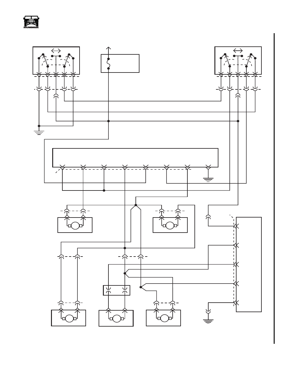
Figure 12-110: Power Locks HMCS W/ Remote Entry
L/R DOOR
LOCK ACTUATOR
R/R DOOR
LOCK ACTUATOR
CARGO DOOR
LOCK ACTUATOR
117 PK
118 BR
FUSE 3H
20A
INTERIOR
G4
1
2
3
4
5
119 TN
E
C17-A
A
B
L
U
3
4
5
2
1
120 LG
517 OR
121 YL
117 PK
118 BR
L/F DOOR
LOCK ACTUATOR
D
E
M
U
L
M
L
U
M
U
L
M
U
L
C22
B
A
R/F DOOR
LOCK ACTUATOR
E
D
B
A
122 PP
9-S12-073
C19
C18
M
U
L
C21
117 PK
G
F
E
D
B
A
C
D
C16
C
D
C14
H
U
L
117 PK
C48
C49
C14
C15-A
C16
56 BK
E
F
A
DRIVER
DOOR
UNLOCK
COMMON
UNLOCK
DOOR
UNLOCK
COMMON
UNLOCK
LOCK
ALL
DOORS
GROUND
58 BK
C31
C30-A
COMMON
UNLOCK
LEFT FRONT DOOR
LOCK SWITCH
RIGHT FRONT DOOR
LOCK SWITCH
BATT
REMOTE ENTRY MODULE (REM)
118 BR
9
6
10
5
GROUND
C47
CARGO DOOR
LOCK MODULE
LOCK
SIGNAL
LOCK
COMMAND
UNLOCK
BATT
121 YL
117 PK
517 OR
59 BK
517 OR
C20-A
C20-B
3
DOOR
CONTACTS
F
B
G4
G4
12-116
Electrical System
______________________________________________________
®
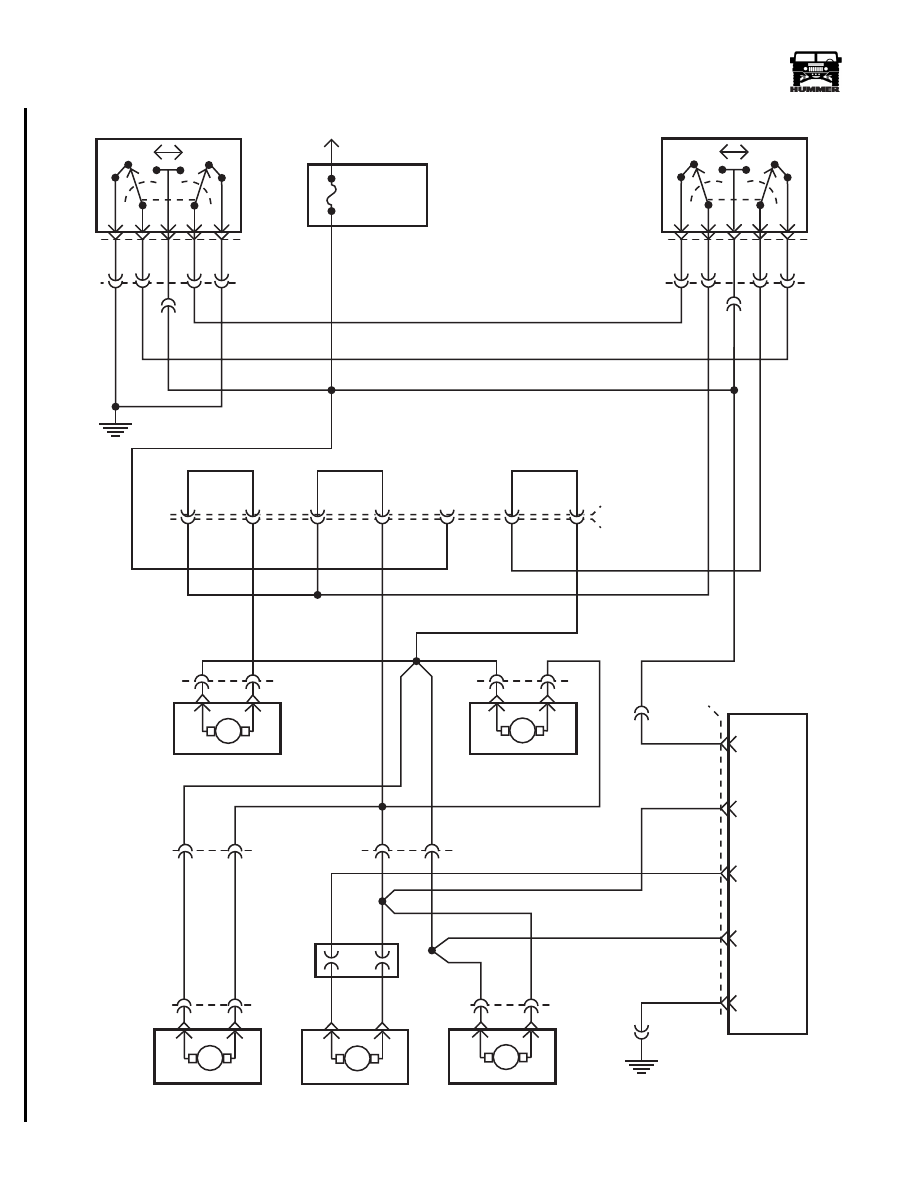
Figure 12-111: Power Locks HMCS W/O Remote Entry
B
L/R DOOR
R/R DOOR
CARGO DOOR
117 PK
118 BR
FUSE 3H
20A
INTERIOR
G4
1
2
3
4
5
119 TN
E
C17-A
A
B
L
U
3
4
5
2
1
120 LG
517 OR
121 YL
1
17 PK
118 BR
L/F DOOR
LOCK ACTUATOR
D
E
M
U
L
M
L
U
M
U
L
M
U
L
C22
B
A
R/F DOOR
LOCK ACTUATOR
E
D
B
A
122 PP
9-S12-075
C19
C18
M
U
L
C21
117 PK
C
D
C16
C
D
C14
U
L
1
17 PK
C48
C49
C14
C15-A
C16
56 BK
E
F
A
LOCK SWITCH
LOCK SWITCH
BATT
118 BR
9
6
10
5
GROUND
C47
CARGO DOOR
LOCK MODULE
LOCK
SIGNAL
LOCK
COMMAND
UNLOCK
BATT
121 YL
117 PK
517 OR
59 BK
517 OR
C20-A
C20-B
3
G
C31
C31 (JUMPER)
F
E
D
B
A
G
F
E
D
B
A
H
H
DOOR
CONTACTS
F
G4
Нет комментариевНе стесняйтесь поделиться с нами вашим ценным мнением.
Текст