Hummer H1 (2002+). Manual — part 223
_____________________________________________________
Electrical System 12-117
®
05745159
H
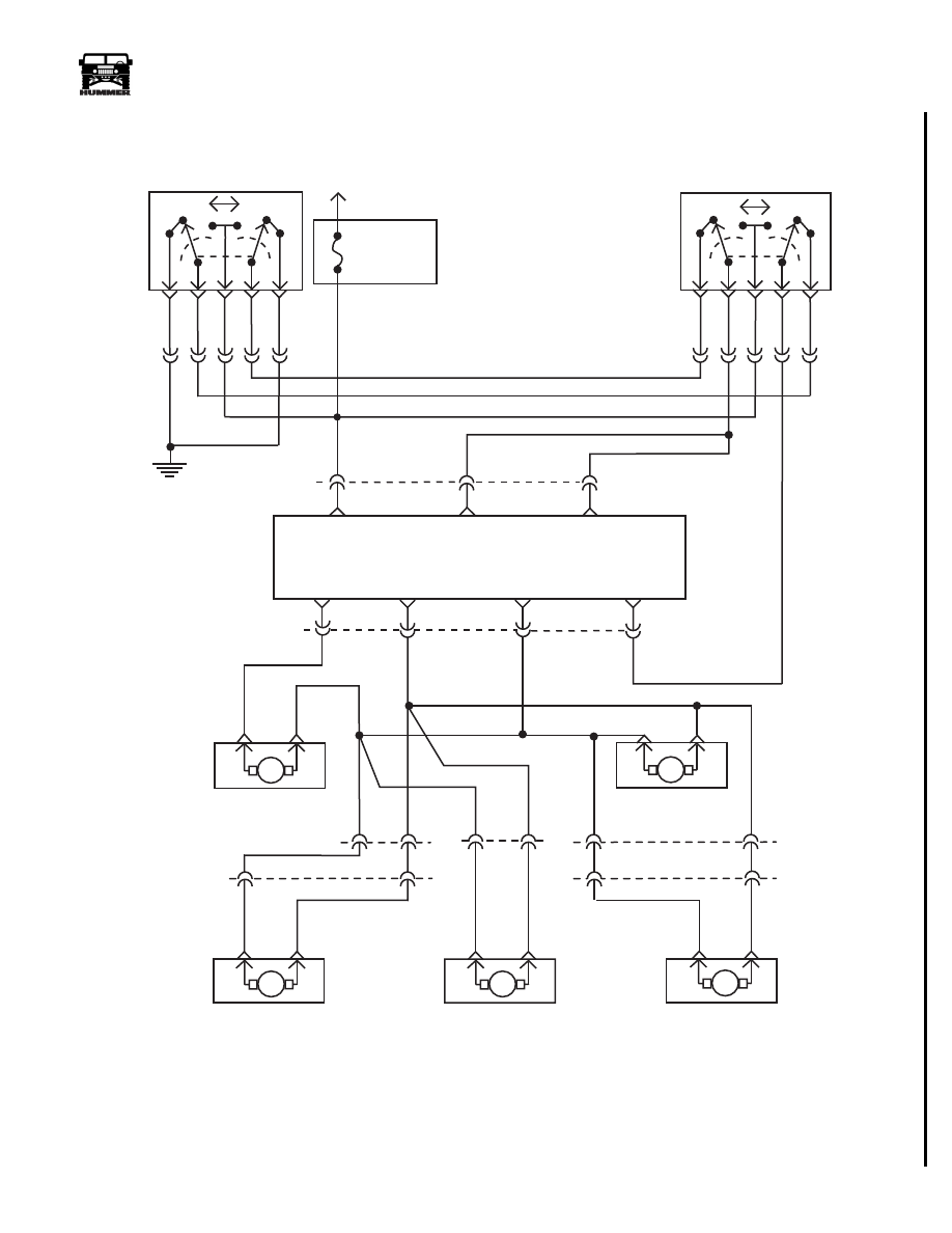
Figure 12-112: Power Locks HMC4, XLC2 , HMSB W/ Remote Entry
FUSE 3H
20A
INTERIOR
HOT AT
ALL TIMES
G4
L
U
1
2
3
4
5
119 TN
C15-F
C14-E
C15-A
C14-A
D
121 YL
C14-B
C16-F
C16-E
C17-A
C16-A
C16-B
L
U
3
4
5
2
1
120 LG
517 OR
F
H
121 YL
C31
BATT
INPUT
COMMON
UNLOCK
REMOTE
ENTRY
MODULE
(REM)
LOCK ALL
DOORS
COMMON
LOCK
COMMON
UNLOCK
PASSENGER
DOOR
UNLOCK
DRIVER’S
DOOR
UNLOCK
G
C31
E
A
B
117 PK
118 BR
L/F DOOR
LOCK MOTOR
E
D
C19
117 PK
M
L
U
M
L
U
M
U
L
M
U
L
C22
B
A
R/F DOOR
LOCK MOTOR
L/R DOOR
LOCK MOTOR
(not used on XLC2)
R/R DOOR
LOCK MOTOR
(not used on XLC2)
D
C18
B
A
122 PP
00-S12-017
F
E
C41
M
U
L
SLANT BACK DOOR
LOCK MOTOR
(HMSB only)
E
C21
1
17 PK
1
18 BR
1
17 PK
1
18 BR
1
17 PK
1
18 BR
12-118
Electrical System
______________________________________________________
®
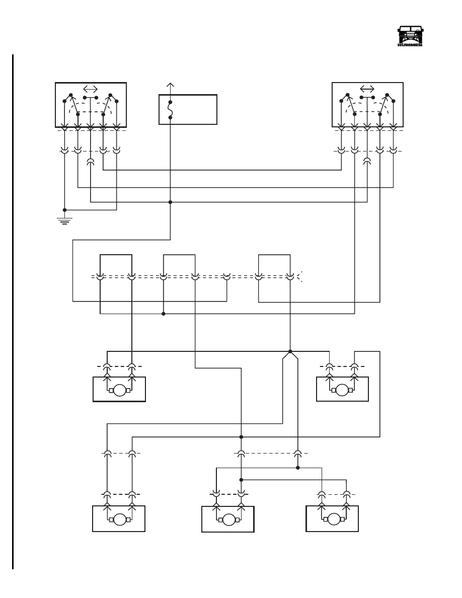
Figure 12-113: Power Locks HMC4, XLC2 , HMSB W/O Remote Entry
L/R DOOR
LOCK ACTUATOR
(not used on XLC2)
R/R DOOR
LOCK ACTUATOR
(not used on XLC2)
SLANT BACK DOOR
LOCK ACTUATOR
(HMSB only)
117 PK
118 BR
FUSE 3H
20A
INTERIOR
BATT
G4
1
2
3
4
5
119 TN
E
C17-A
A
B
L
U
3
4
5
2
1
120 LG
517 OR
121 YL
G
C31
1
17 PK
118 BR
L/F DOOR
LOCK ACTUATOR
D
E
M
U
L
M
L
U
M
U
L
M
U
L
C22
B
A
R/F DOOR
LOCK ACTUATOR
E
D
B
A
122 PP
00-S12-016
C19
C18
F
E
M
U
L
C41
C21
117 PK
118 BR
C31 (JUMPER)
F
E
D
B
A
G
F
E
D
B
A
C
D
C16
C
D
C14
H
H
U
L
117 PK
C48
C49
C14
C15-A
C16
56 BK
E
F
A
LEFT FRONT DOOR
LOCK SWITCH
RIGHT FRONT DOOR
LOCK SWITCH
F
B
_____________________________________________________
Electrical System 12-119
®
05745159
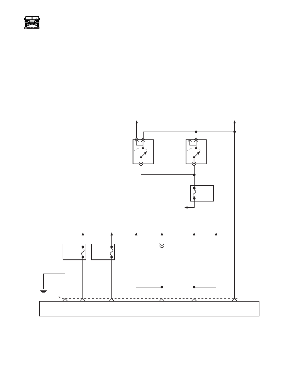
Figure 12-114: Remote Entry Module Power/Ground
FUSE
1H
5 AMP
INTERIOR
FUSE
7B
5 AMP
INTERIOR
G4
A
58 BK
554 GY
840 DG
BATT
IGNITION
C1-62
TO HORN
SWITCH ON
STEERING
COLUMN
TO PARK
LAMP
SWITCH
TO HORN
RELAY
TO PARK
LIGHT
1 DB
14 LB
53 LB
FUSE
5 H
15 AMP
INTERIOR
TO CHIME
TO DOME
LAMPS
LF DOOR
JUMP
SWITCH
RF DOOR
JUMP
SWITCH
54 DG
53 LB
REMOTE ENTRY MODULE
GROUND
BATT
IGN
HORN
ACTIUATION
PARK
LIGHT
FLASH
DOME
LAMPS
ACTIUATION
9-S12-065
C30
G
F
E
H
D
BATT
12-120
Electrical System
______________________________________________________
®
POWER DOOR LOCK FRONT DOOR HARNESS
REPLACEMENT
Removal
NOTE: Left and right front power door lock harness replace-
ment procedures are similar.
1.
Remove front seat.
2.
Remove outer kick panels.
3.
Remove power door locks switch from door trim.
4.
Remove front door trim.
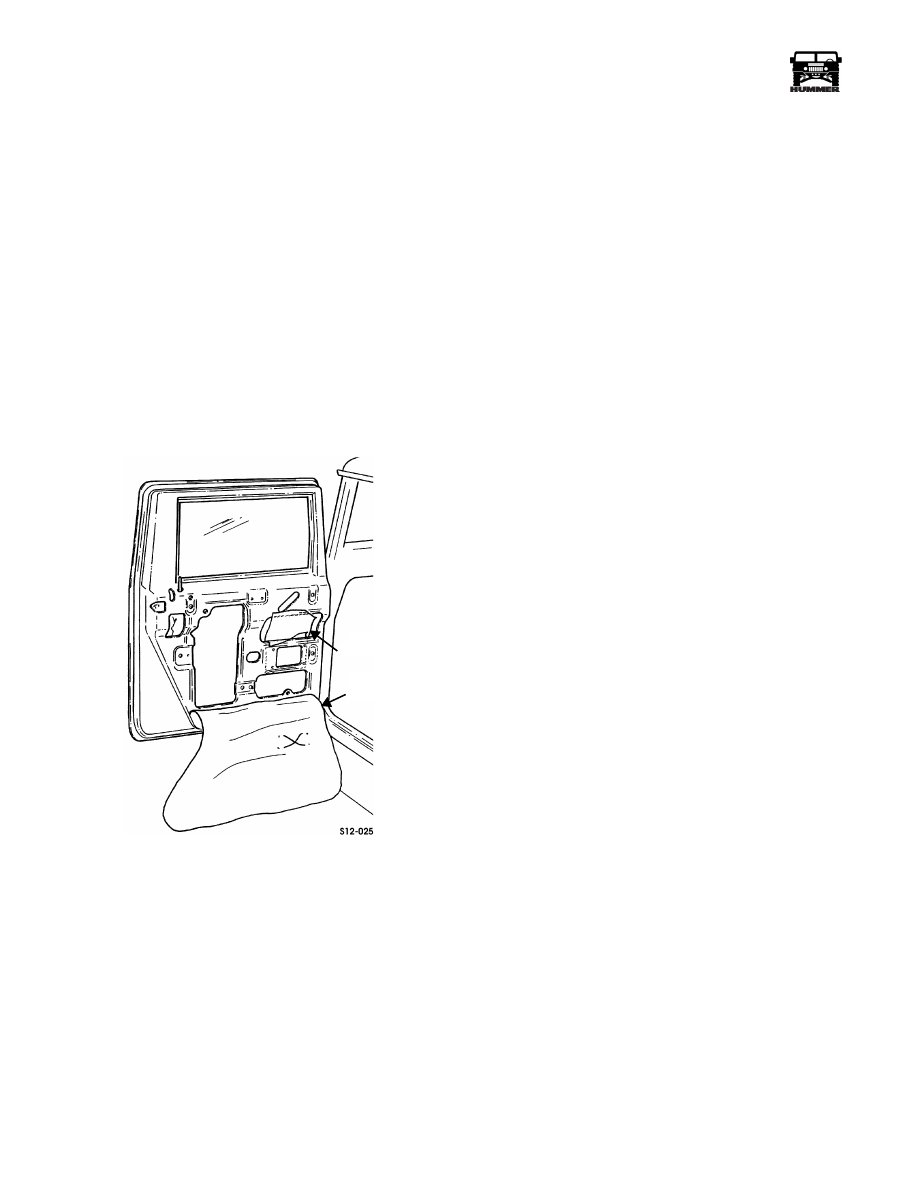
NOTE: Vapor barrier may be positioned under velcro strip, if
so, cut around velcro strip to remove vapor barrier.
5.
Remove vapor barrier and moisture barrier flap from door
(Figure 12-115).
Figure 12-115: Vapor Barrier
6.
Remove capscrew and clamp securing door harness to
door reinforcement.
7.
Remove capscrew, nut and lockwasher assembly, and P-
clamp securing door harness to A-pillar.
8.
Disconnect harness from lock motor, window motor and
mirror (if equipped).
9.
Disconnect four-lead and six-lead connectors. Remove
door harness wires from connectors with extraction tool.
Note position of wires for installation of the new harness.
NOTE: Lubricate bushings, grommet, and door harness teflon
cover with silicone spray.
10. Pull harness through A-pillar rubber grommet.
11. Remove and inspect A-pillar rubber grommet. Discard if
damaged.
12. Remove two capscrews and support bracket from inner
door.
13. Pull harness through door bushing. Inspect door bushing.
Replace if damaged.
14. Pull support bracket from harness. Inspect support bracket
bushing. Replace if damaged.
15. Disconnect clip from door reinforcement and remove from
door harness.
16. Remove tie strap securing door harness to access hole and
remove harness. Discard tie strap.
Installation
1.
Install harness in support bracket.
2.
Install harness through door bushing and support bracket.
Install support bracket on inner door with two capscrews.
3.
Install rubber grommet in A-pillar.
4.
Install harness through grommet until yellow tape touches
A-pillar front.
5.
Install six-lead and one-lead connectors to door harness
leads, matching colors to dash harness. Connect door
harness to dash harness.
6.
Install P-clamp and door harness on A-pillar with
capscrew and nut and lockwasher assembly.
7.
Install clamp and door har
8.
ness at yellow tape area with capscrew.
9.
Install clip on door harness and connect harness to door
lock actuator, window motor and power mirror (if
equipped) Lower window.
10. Route lock switch lead up through lower access hole
between support bracket and window channel. Secure at
top access hole with tie strap (left front door only).
NOTE: Vapor barrier must be completely sealed at all edges to
prevent water entry into the interior of the vehicle.
11. Route lock switch lead through vapor barrier and moisture
barrier flap and install moisture barrier and vapor barrier
flap on door.
12. Install front door trim.
13. Install power door locks switch.
14. Install outer kick panels.
15. Install front seat.
16. Verify operation.
VAPOR
BARRIER
MOISTURE
BARRIER FLAP
Нет комментариевНе стесняйтесь поделиться с нами вашим ценным мнением.
Текст