Hummer H1 (2002+). Manual — part 106
______________
Wheels and Tires/Central Tire Inflation System (CTIS) 6-39
®
05745159
COMPRESSOR/LOW PRESSURE INDICATOR
LIGHTS
Removal
1.
Remove lower closeout panel and swing steering column
down.
2.
Loosen center console and pull back to allow removal of
left crash pad.
3.
Pull instrument panel back to gain access to the back of
the status centers.
4.
Turn lamp one quarter turn, and remove lamps from
sockets.
Cleaning and Inspection
Clean and inspect indicator lamps for damage. Replace defec-
tive parts.
Installation
1.
Install lamps in sockets and turn one quarter turn
(Figure 6-56).
2.
Install instrument panel.
3.
Install left crash pad and center console.
4.
Install steering column and lower closeout panel.
5.
Start engine, and operate CTIS system to ensure lamps and
switch operate properly.
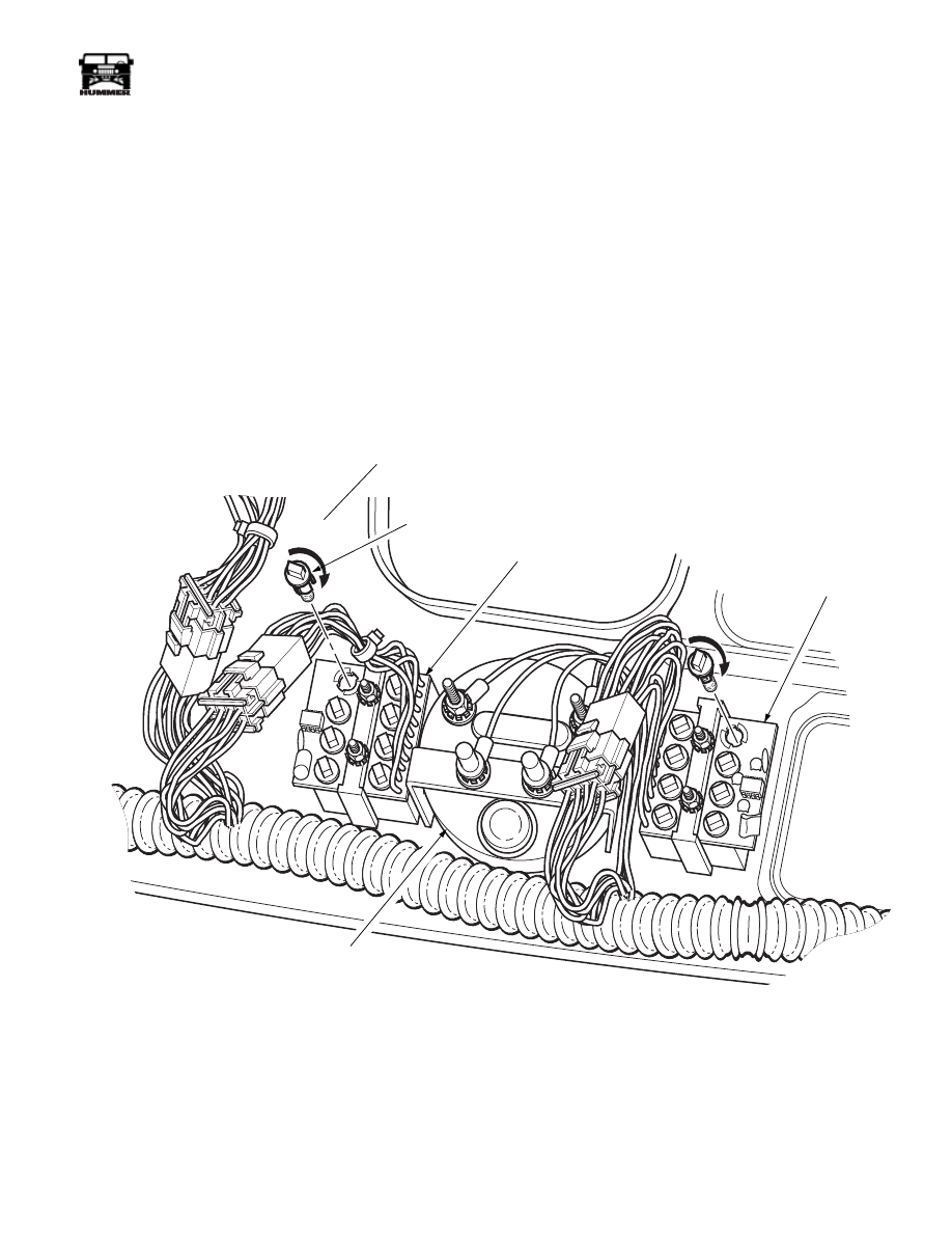
Figure 6-56: Compressor/Low Pressure Indicator Lights
9-S06-015
9-S06-015
BACKSIDE OF
INSTRUMENT PANEL
BULB
HOLDER
STATUS
CENTER
STATUS
CENTER
SPEEDOMETER
~
6-40
Wheels and Tires/Central Tire Inflation System (CTIS)
_______________
®
AIR PRESSURE GAUGE
WARNING: CTIS components are subject to high air
pressure. Always relieve air pressure before loosening
or removing air system components by disconnecting
quick-disconnect valve assemblies. Failure to follow
this warning may result in serious injury.
Removal
1.
Remove CTIS instrument cluster panel.
2.
Remove lamp from air pressure gauge (Figure 6-57).
3.
Disconnect two air pressure indicator lines from air
pressure gauge.
4.
Remove two nuts, lockwashers, air pressure gauge, and
bracket from CTIS instrument cluster (Figure
6-57).
Discard lockwashers.
Cleaning and Inspection
Clean and inspect air pressure gauge and lamp. Check for
cracks and stripped threads. Replace defective parts.
CAUTION: Do not allow sealant into air system. Sealant will
damage CTIS components.
NOTE: Apply sealant to threads prior to installation.
Installation
1.
Install air pressure gauge and bracket on CTIS instrument
cluster with two nuts and lockwashers. Tighten nuts to 8
lb-in. (0.9 N•m) (Figure 6-57).
2.
Connect two air pressure indicator lines to air pressure
gauge.
3.
Install lamp in air pressure gauge.
4.
Install CTIS instrument cluster panel.
5.
Start engine and ensure air pressure gauge operates
properly.
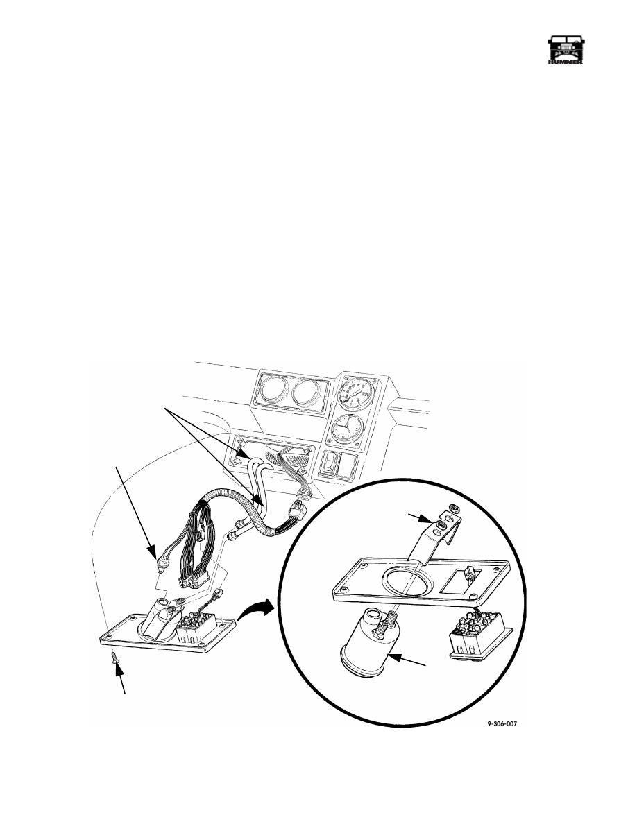
Figure 6-57: Air Pressure Gauge
AIR PRESSURE
GAUGE
AIR PRESSURE
INDICATOR
LINES
SCREW
PRESSURE
GAUGE LAMP
AIR PRESSURE
GAUGE BRACKET
______________
Wheels and Tires/Central Tire Inflation System (CTIS) 6-41
®
05745159
AIR PRESSURE GAUGE LAMP REPLACEMENT
Removal
1.
Remove lower closeout panel and swing steering column
down.
2.
Loosen center console and pull back to allow removal of
left crash pad.
3.
Pull instrument panel back to gain access to the back of
the status centers.
4.
Turn lamp one quarter turn, and remove lamps from
sockets.
Installation
1.
Install lamps in sockets and turn one quarter turn
(Figure 6-56).
2.
Install instrument panel.
3.
Install left crash pad and center console.
4.
Install steering column and lower closeout panel.
5.
Start engine, and operate CTIS system to ensure lamp and
switch operate properly.
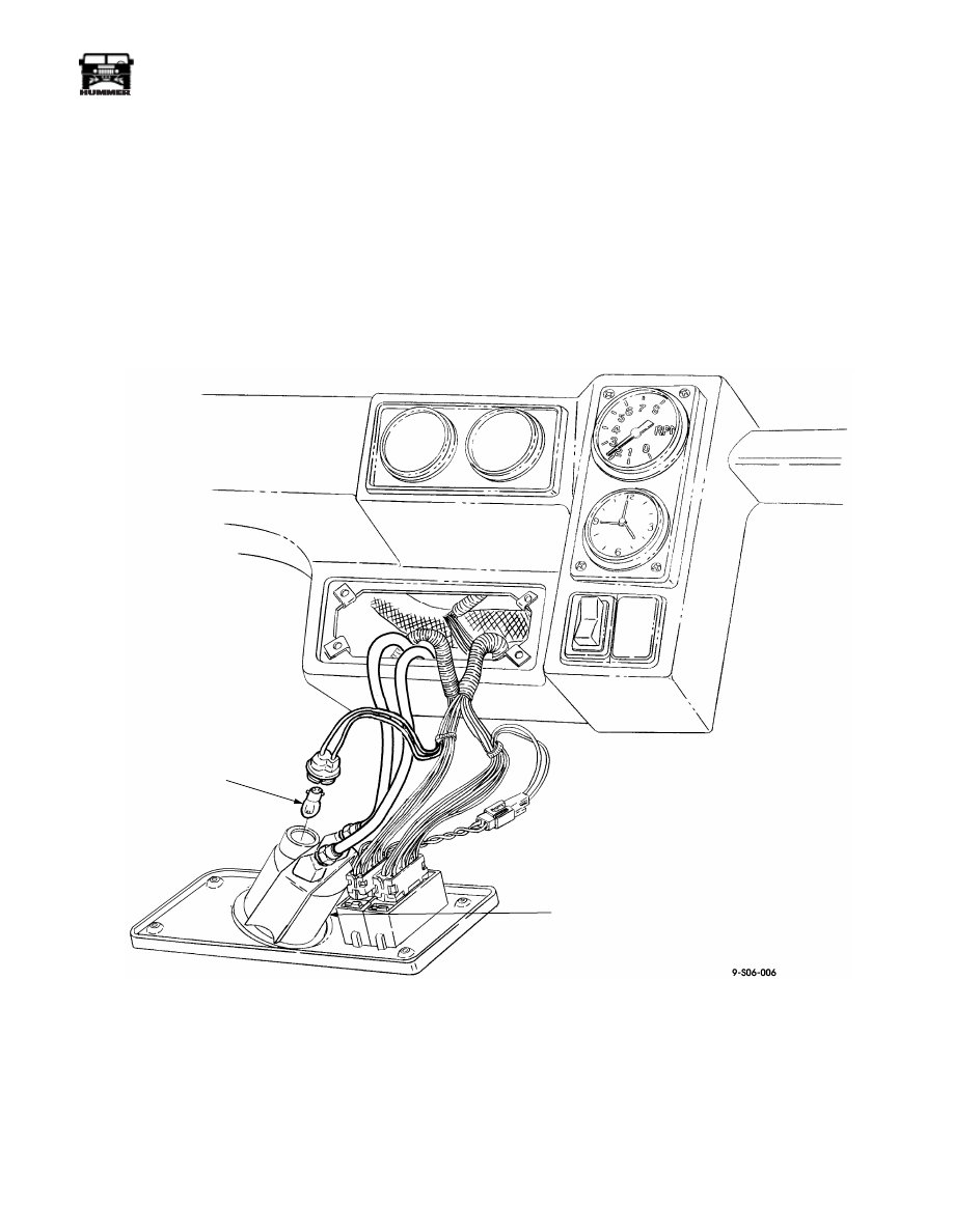
Figure 6-58: Air Pressure Gauge Lamp
AIR PRESSURE
GAUGE LAMP
AIR PRESSURE
GAUGE
6-42
Wheels and Tires/Central Tire Inflation System (CTIS)
_______________
®
CTIS LOW PRESSURE ALARM REPLACEMENT
Removal
1.
Remove the interior fuse box access panel in the left close-
out panel under the instrument panel.
2.
Remove the low pressure alarm from the face of the
interior fuse box (Figure 6-59).
Installation
1.
Install low pressure alarm on the interior fuse box.
2.
Install the fuse box access panel in the left closeout panel.
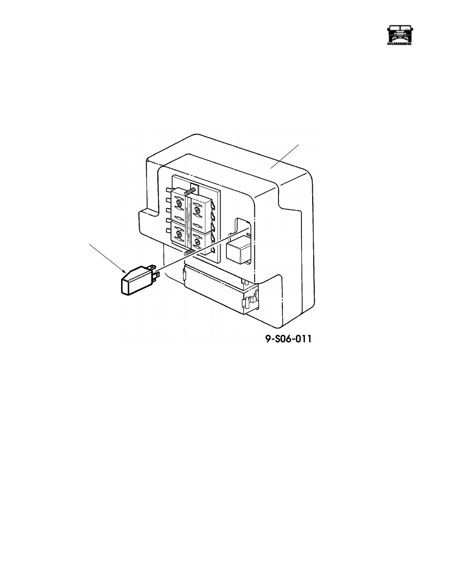
Figure 6-59: Low Pressure Alarm Location
LOW
PRESSURE
ALARM
INTERIOR
FUSE
BOX
~
Нет комментариевНе стесняйтесь поделиться с нами вашим ценным мнением.
Текст