Hummer H1 (2002+). Manual — part 171
_____________________________________________________________________
Body 10-55
®
05745159
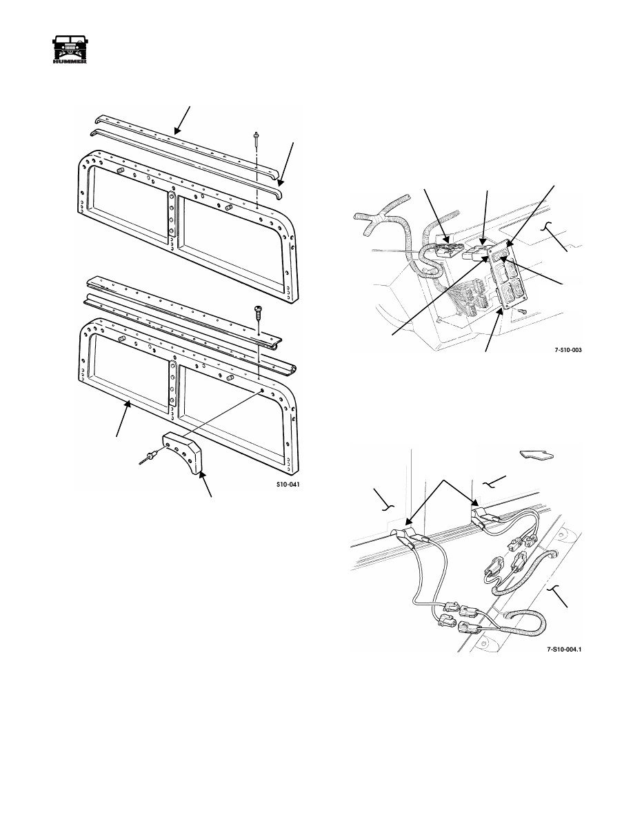
Figure 10-105: Windshield Assembly Seal
Replacement
Installation
1.
Position two seals on windshield assembly
(Figure 10-103).
2.
Position windshield assembly over A-pillar.
3.
Secure windshield assembly to two brackets with six bolts
and washers.
4.
Connect two jumper harness leads to body harness leads
and insert grommet into windshield center pillar
(Figure 10-104).
5.
Secure windshield assembly to A-pillar with two bolts and
locknuts (Figure 10-103).
6.
Install windshield wiper arm pivots.
7.
Install windshield wiper linkage.
8.
Install windshield wiper arm and blade.
9.
Install soft top.
HEATED WINDSHIELD
The optional heated windshield is capable of defrosting the
windshield glass in less than 10 minutes at 0° F. The system is
comprised of a rocker switch with an integrated time delay
module (Figure 10-106), two relays, and two fuses , and in-
glass heating elements.
Figure 10-106: Rocker Switch/Time Delay Module
Location
Figure 10-107: Heating Element Junction
Location
The rocker switch/time delay module is mounted on the power
window master switch on the driver side of the front console
(Figure 10-106).
FORMER
SEAL
CORNER CAP
WINDSHIELD
ASSEMBLY
CONNECTOR
TIME DELAY
MODULE
ROCKER
FRONT
CLIPS
POWER WINDOW
MASTER SWITCH
ASSEMBLY
(NOT SHOWN)
CONSOLE
SWITCH
LIGHT
INDICATOR
DRIVER
SIDE
WINDSHIELD
GLASS
PASSENGER SIDE
WINDSHIELD GLASS
FRONT
CONSOLE
HEATING
ELEMENT
JUNCTIONS

10-56
Body
______________________________________________________________________
®
Removal
NOTE:
Wire harnesses behind console are long enough to al-
low for power window master switch removal without remov-
ing console for access to electrical connectors.
1.
Remove screws and pull power window master switch
from console (Figure 10-106).
2.
Lift connector clip and pull connector from rocker switch/
time delay module.
3.
Squeeze clips on rocker switch/time delay module and
remove switch/module from bezel.
Installation
1.
Push rocker switch/time delay module into bezel opening
and snap into bezel.
2.
Attach electrical connector to rocker switch/time delay
module.
3.
Install power window master switch in console.
WINDSHIELD WIPER SYSTEM AND
COMPONENTS
Windshield Wiper Motor Assembly
Replacement
Removal
1.
Remove center trim from windshield assembly.
2.
Remove roof mounted amplifier cover/speaker housing if
equipped.
3.
Disconnect windshield wiper motor assembly harness
from crossbody harness (Figure 10-108).
4.
Remove three bolts, washers, and lockwashers securing
windshield wiper motor assembly to windshield assembly.
5.
Remove retainer securing windshield wiper linkage to
windshield wiper motor cranking pin and remove
windshield wiper motor assembly.
Installation
1.
Lubricate windshield wiper motor cranking pin and secure
windshield wiper linkage to windshield wiper motor
cranking pin with retainer (Figure 10-108).
2.
Secure windshield wiper motor assembly to windshield
assembly with three lockwashers, washers, and bolts.
Tighten bolts to 12 lb-ft (16 N•m).
3.
Connect windshield wiper motor assembly harness to
crossbody harness.
4.
Install roof mounted amplifier cover/speaker housing if
removed earlier.
5.
Secure center trim to windshield assembly.
Figure 10-108: Windshield Wiper Motor Assembly
Replacement
9-S10-011
WINDSHIELD
LINKAGE
WINDSHIELD WIPER
MOTOR ASSEMBLY
ASSEMBLY
WINDSHIELD WIPER
WINDSHIELD WIPER
MOTOR CRANKING PIN
WINDSHIELD WIPER MOTOR
ASSEMBLY HARNESS
RETAINER

_____________________________________________________________________
Body 10-57
®
05745159
Windshield Wiper Linkage Replacement
Removal
NOTE:
Left and right side windshield wiper linkage replace-
ment procedure is the same. This procedure covers the left side.
1.
Remove windshield wiper motor assembly.
2.
Remove upper A-pillar trim.
3.
Disconnect windshield wiper linkage from windshield
wiper pivot cranking lever pin and remove windshield
wiper linkage (Figure 10-109).
Installation
1.
Secure windshield wiper linkage to windshield wiper pivot
cranking lever pin (Figure 10-109).
2.
Install upper A-pillar trim.
3.
Install windshield wiper motor assembly on windshield
assembly.
Figure 10-109: Windshield Wiper Linkage
Replacement
Windshield Wiper Pivot Replacement
Removal
NOTE:
Left and right side windshield wiper pivot replacement
procedure is the same. This procedure covers the left side.
1.
Remove windshield wiper arm assembly.
2.
Remove upper A-pillar trim.
3.
Remove windshield wiper linkage from windshield wiper
pivot cranking lever pin (Figure 10-110).
4.
Remove nut, washer, and rubber washer securing
windshield wiper pivot to windshield assembly and
remove windshield wiper pivot.
Installation
1.
Secure windshield wiper pivot to windshield assembly
with rubber washer, washer and nut (Figure 10-110).
2.
Secure windshield wiper linkage to windshield wiper
pivot cranking lever pin.
3.
Install upper A-pillar trim.
4.
Install windshield wiper arm assembly.
Figure 10-110: Windshield Wiper Pivot
Replacement
WINDSHIELD
ASSEMBLY
WINDSHIELD WIPER PIVOT
LINKAGE
WINDSHIELD WIPER
CRANKING LEVER PIN
WINDSHIELD WIPER
WINDSHIELD
WINDSHIELD
WINDSHIELD
WINDSHIELD WIPER PIVOT
CRANKING LEVER PIN
WIPER LINKAGE
ARM ASSEMBLY
WIPER PIVOT
ASSEMBLY

10-58
Body
______________________________________________________________________
®
WINDSHIELD WASHER SYSTEM AND
COMPONENTS
Reservoir and Pump Assembly
Replacement
Removal
1.
Drain reservoir.
2.
Remove two screws and retaining bracket securing ABS
ECU enclosure. Set aside ECU with enclosure.
3.
Disconnect pump connector from reservoir and pump
assembly (Figure 10-111).
4.
Disconnect fluid level connector from fluid level sensor
assembly.
5.
Remove four bolts, lockwashers, and reservoir assembly
from reservoir support assembly.
6.
Disconnect windshield washer hose from reservoir and
pump assembly.
7.
Inspect wellnuts for damage. Replace if damaged.
Figure 10-111: Windshield Washer Fluid Reservoir
and Pump Replacement
Installation
1.
Connect windshield washer hose to reservoir and pump
assembly.
2.
Secure reservoir assembly to reservoir support assembly
with four lockwashers and bolts. Tighten bolts to 8 lb-ft
(11 N•m) (Figure 10-111).
3.
Connect fluid level connector to fluid level sensor
assembly.
4.
Connect pump connector to pump assembly.
5.
Secure ABS ECU enclosure with retaining bracket and
two screws.
6.
Fill reservoir.
Windshield Washer Nozzle Replacement
Removal
1.
Disconnect hose from nozzle (Figure 10-112).
2.
Remove screw and nozzle from body.
Installation
1.
Secure nozzle to body with screw.
2.
Connect hose to nozzle.
Windshield Washer Hose Replacement
Removal
1.
Remove two nuts, washers, screws, washers, and clamps
securing hose to body (Figure 10-113).
2.
Remove two screws and retaining bracket securing ABS
ECU enclosure. Set aside ECU with enclosure.
3.
Disconnect washer hose from pump and tee. Remove
clamps from hose.
4.
Disconnect two hoses from tee and nozzles and remove
from clamps.
Installation
1.
Slide two hoses through clamps and connect to tee and
nozzles.
2.
Slide hose through clamps and connect to tee and pump.
3.
Secure hose to body with two clamps, washers, screws,
washers, and nuts.
4.
Secure ABS ECU enclosure with retaining bracket and
two screws.
WINDSHIELD
RESERVOIR
ASSEMBLY
RESERVOIR
WASHER
HOSE
SUPPORT
ASSEMBLY
FLUID LEVEL
CONNECTOR
PUMP CONNECTOR
Нет комментариевНе стесняйтесь поделиться с нами вашим ценным мнением.
Текст