Hummer H1 (2002+). Manual — part 219
_____________________________________________________
Electrical System 12-101
®
05745159
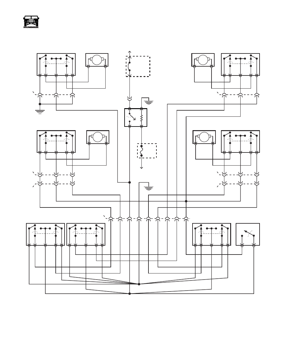
Figure 12-101: Power Window Schematic
226 YL
313 DB
C15
227 RD
226 YL
B
D
C
G4
9-S12-011
M
M
LEFT FRONT DOOR
WINDOW SWITCH
( ALL MODELS )
LEFT FRONT DOOR
WINDOW MOTOR
4
5
3
1
2
RIGHT FRONT DOOR
WINDOW MOTOR
RIGHT FRONT DOOR
WINDOW SWITCH
( ALL MODELS )
4
5
3
1
2
56 BK
314 WT
227 RD
226 YL
C
D
B
170 PP
C22
227 RD
C
E
D
M
M
LEFT REAR DOOR
WINDOW SWITCH
( ALL MODELS )
LEFT REAR DOOR
WINDOW MOTOR
4
5
3
1
2
RIGHT REAR DOOR
WINDOW MOTOR
RIGHT REAR DOOR
WINDOW SWITCH
( ALL MODELS )
4
5
3
1
2
319 TN
227 RD
226 YL
D
E
C
170 PP
320 LG
171 RD
CONSOLE
LEFT REAR
WINDOW SWITCH
4
5
3
1
2
CONSOLE
RIGHT REAR
WINDOW SWITCH
4
5
3
1
2
CONSOLE
RIGHT FRONT
WINDOW SWITCH
4
5
3
1
2
170 PP
C6
K8
K9
E1
E2
P9
P8
P6
317 LG
170 PP
316 TN
C19
B
G
C
C
G
B
CONSOLE
WINDOW LOCK
SWITCH
58 BK
171 RD
POWER
WINDOW
RELAY R4
G4
59 BK
TO
BATT
EXTERIOR
FUSE BOX
175 LB
G7
F7
F5
G5
5M
30 AMP
CIRCUIT
BREAKER
INTERIOR
FUSE BOX
FUSE
2G
5 AMP
TO
IGNITION
C1-69
A1
H6
C17
C21
C18
G4
296 DG
POWER WINDOWS
4-1-00
12-102
Electrical System
______________________________________________________
®
POWER DOOR LOCK SWITCH REPLACEMENT
NOTE: Switch replacement is the same for all doors.
Removal
1.
Remove mounting plate, capscrews, and remove switch
from switch bezel (Figure 12-102).
2.
Disconnect door harness from switch.
Separate switch from mounting plate.
Installation
1.
Assemble switch and mounting plate.
2.
Connect switch to door harness.
3.
Install switch and mounting plate on bezel and secure with
screws.
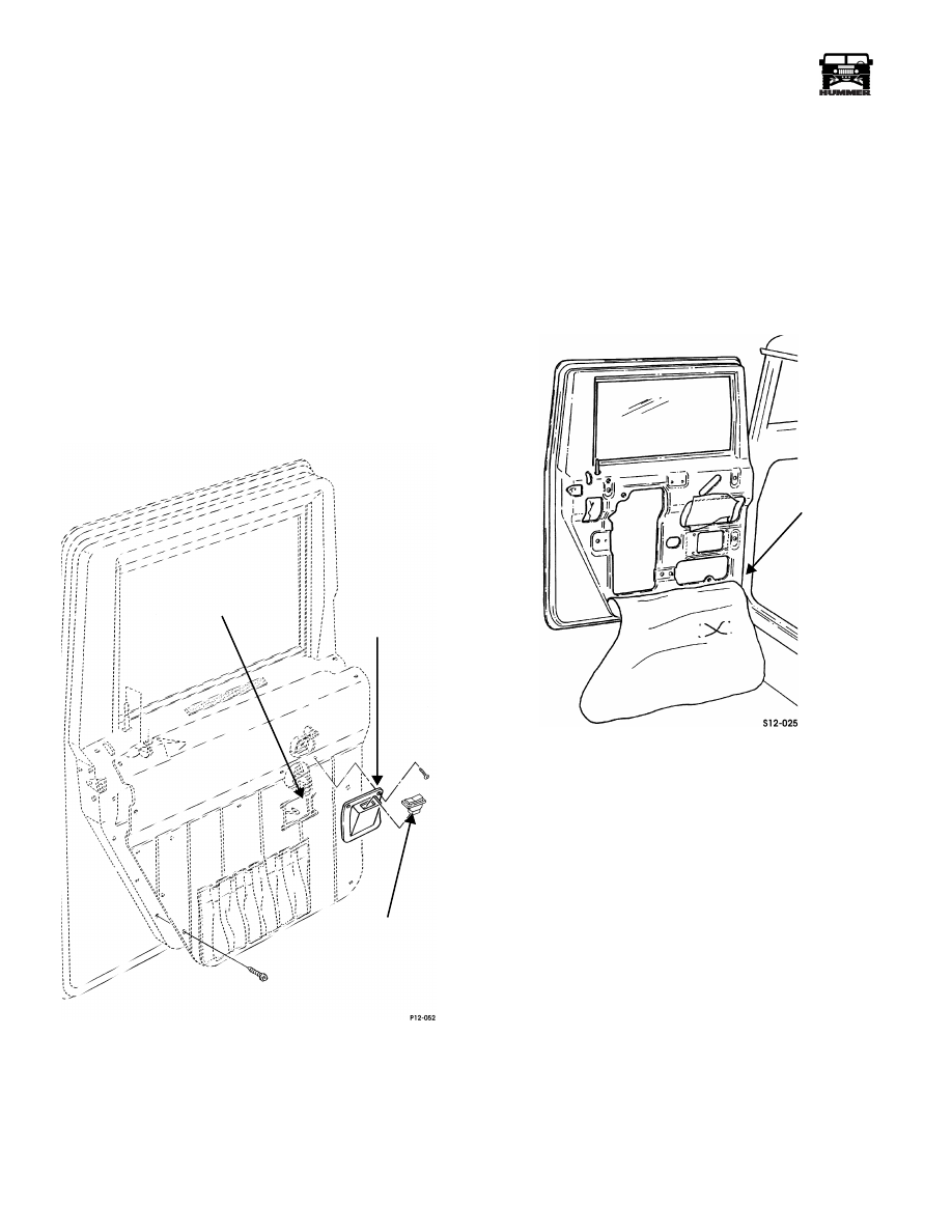
Figure 12-102: Power Door Lock Switch Mounting
POWER DOOR LOCK ACTUATOR
REPLACEMENT
Removal
NOTE: Actuator replacement is the same for all doors.
1.
Raise window.
2.
Remove door trim panel.
3.
Remove vapor barrier (Figure 12-103).
Figure 12-103: Vapor Barrier Removal/Installation
4.
Detach door harness connector from door actuator
(Figure 12-104).
DOOR
HARNESS
SWITCH
BEZEL
SWITCH
VAPOR
BARRIER
4-1-00
_____________________________________________________
Electrical System 12-103
®
05745159
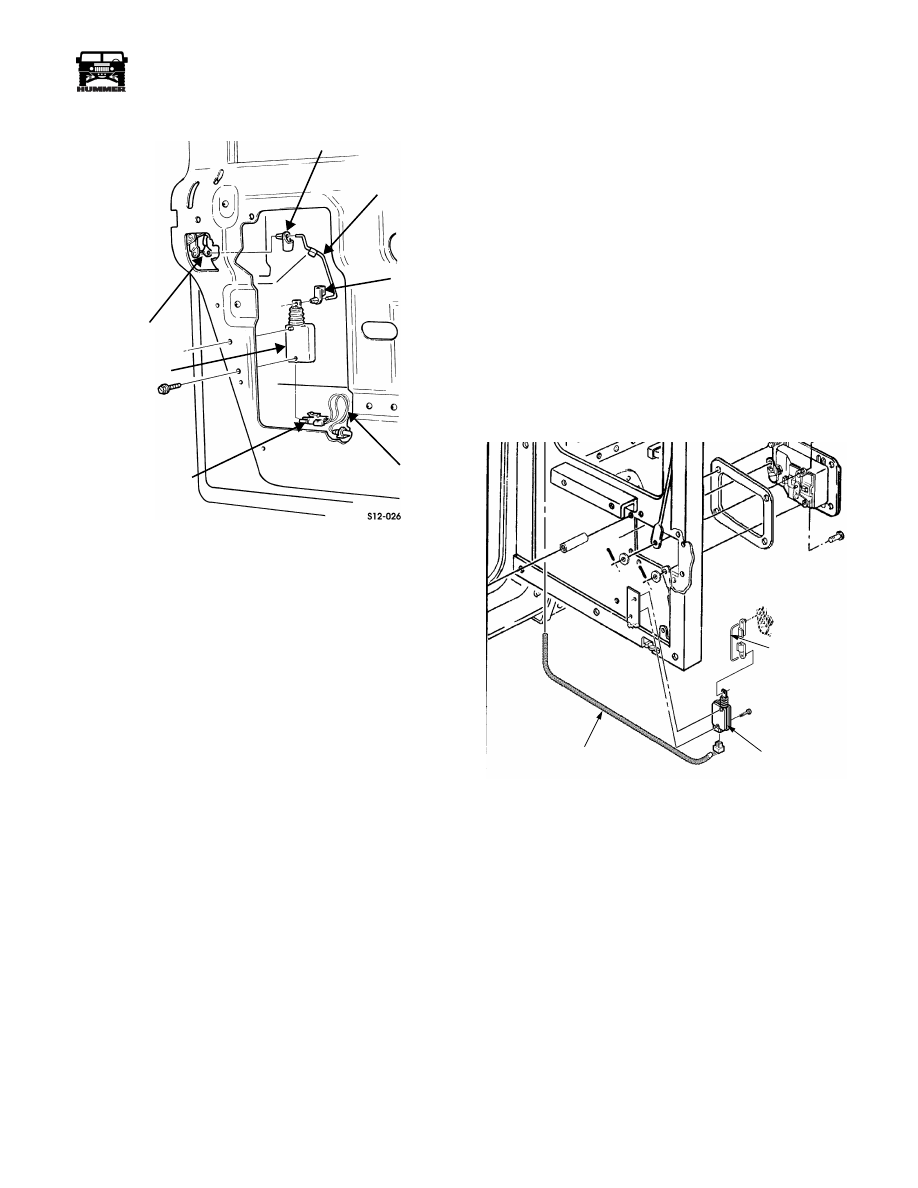
Figure 12-104: Door Lock Actuator
Removal/Installation
5.
Remove actuator attaching screws.
6.
Remove actuator from door and disconnect actuator rod
from clips and actuator.
Installation
NOTE: Color coding on actuator rod is positioned away from
actuator during installation. Actuator rods are color coded as
follows: left front, red; right front, green; left rear, yellow; and
right rear, blue.
1.
Connect clip and actuator rod to lock lever
(Figure 12-104).
2.
Install opposite clip on actuator and connect rod to
actuator.
3.
Secure actuator with mounting screws.
CAUTION: The actuator threads will strip if overtightened.
4.
Connect harness wires to actuator.
NOTE: Vapor barrier must be completely sealed at all edges to
prevent water entry into the interior of the vehicle.
5.
Install vapor barrier (Figure 12-103).
6.
Install door trim panel.
Door Lock Actuator Replacement For Rear
Cargo Door (HMCS Only)
Removal
1.
Remove window from primary rear door.
2.
Remove (4) screws and interior door handle.
3.
Remove (12) screws securing inner door panel to door.
4.
Remove inner door panel.
5.
Disconnect link rod from lock actuator by rotating plastic
lock clip clockwise.
6.
Remove link rod from plastic clip, and plastic clip from
actuator.
7.
Remove screw securing door lock actuator to bracket.
8.
Disconnect door lock harness from actuator.
9.
Remove actuator from bracket (Figure 12-105).
Figure 12-105: Cargo Door Lock Actuator
Installation
1.
Connect door lock harness to new door lock actuator.
2.
Place actuator on bracket so actuator plunger is on the left
side of the actuator.
3.
Install screw securing door lock actuator to bracket.
4.
Install plastic clip into hole in actuator plunger.
5.
Install link rod into plastic clip and rotate counter
clockwise to lock in place (Figure 12-105).
6.
Install inner door pane with (12) screws.
7.
Install inner door handle with (4) screws.
8.
Verify operation of door handle and door locks.
CLIP
ACTUATOR
ROD
CLIP
DOOR
HARNESS
HARNESS
CONNECTOR
LOCK
LEVER
ACTUATOR
ACTUATOR
ACTUATOR HARNESS
LINK ROD
4-1-00

12-104
Electrical System
______________________________________________________
®
Rear Cargo Door Lock Module Replace-
ment (HMCS Only).
Removal
1.
Remove right rear seat.
2.
Remove right rear seat belt ratchet assembly.
3.
Remove right rear corner trim assembly (Figure 12-106).
Figure 12-106: Removing Right Rear Trim Piece
4.
Disconnect rear door lock harness jumper assembly from
the rear door lock module.
5.
Pull the module loose from the velcro attaching it to the
body.
Installation
1.
Apply new velcro strip to new rear door lock module
2.
Affix new module to body and connect rear door lock
harness jumper.
3.
Verify operation of rear door locks.
4.
Install right rear trim piece (Figure 12-106).
5.
Apply loctite 242 to seat belt ratchet bolt.
6.
Install seat belt ratchet bolt and torque to 35-40 ft-lbs
(47-55 Nm).
7.
Install right rear seat.
Rear Cargo Door Lock Harness Jumper
Replacement
Removal
1.
Remove right rear seat.
2.
Remove right rear seat belt ratchet assembly.
3.
Remove right rear corner trim assembly (Figure 12-106).
4.
Disconnect harness from rear door lock module.
5.
Remove slide out bulkhead.
6.
Remove closeout panel from passenger side of rear cargo
door frame.
7.
Disconnect harness from door hinge contacts.
8.
Pull the padding and carpet on the cargo area wall upward
to expose the harness.
9.
Remove remaining trim pieces behind right rear passenger
seat.
10. Remove lower passenger side B-pillar trim.
11. Remove passenger side righthand kick panel.
12. Disconnect rear cargo door lock jumper.
13. Remove the harness from the vehicle.
Installation
1.
Connect rear cargo door lock jumper harness to the con-
nector at the B-Pillar.
2.
Route harness along same locations to the rear cargo door
lock module.
3.
Connect the harness to the door lock module.
4.
Route harness to the door hinge contacts and connect it.
5.
Install passenger side cargo door frame closeout panel.
6.
Reposition the cargo area padding.
7.
Install trim pieces behind right rear passenger seat.
8.
Install rear passenger righthand side kick panel.
9.
Install passenger side lower B-pillar trim.
10. Install removable cargo area bulkhead.
11. Install passenger right rear seat.
RIGHT REAR CORNER
TRIM ASSEMBLY
CARGO BULKHEAD
4-1-00
Нет комментариевНе стесняйтесь поделиться с нами вашим ценным мнением.
Текст