Hummer H1 (2002+). Manual — part 217

______________________________________________________
Electrical System 12-93
®
05745159
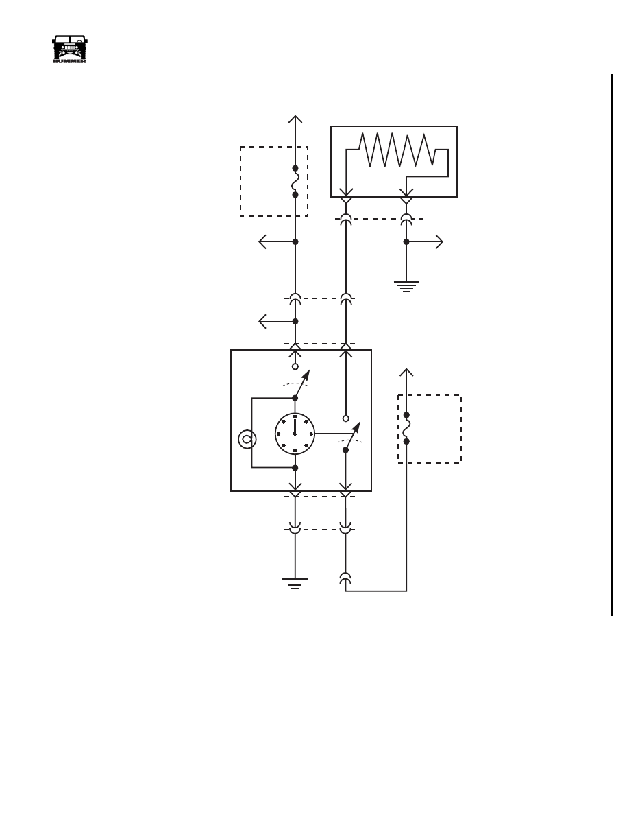
Figure 12-99: Heated Windshield Schematic
59 BK
FUSE
2C
30 AMP
EXTERIOR
FUSE
BOX
FUSE
2D
30 AMP
EXTERIOR
FUSE
BOX
FUSE
1C
5 AMP
INTERIOR
FUSE
BOX
HEATED
WINDSHIELD
SWITCH
TO
IGNITION
LEFT WINDSHIELD
RIGHT WINDSHIELD
17 PP
58 BK
83 TN
C6-M7
C1-33
580 BR
R-4
LEFT
WINDSHIELD
RELAY
R-2
RIGHT
WINDSHIELD
RELAY
HEATED
WINDSHIELD
RELAYS
G4
59 BK
740 YL
739 PP
59 BK
G1
G1
TO
BATTERY
TO
BATTERY
G4
C1-3
C1-2
TO
DIMMER SWITCH
TO
COMPASS/MIRROR
RELAY
9-S12-009
C6-F3
C6-M8
C6-M6
738 RD
737 OR
TO
HEATED
MIRRORS
HEATED WINDSHIELDS
4-1-00

12-94
Electrical System
_______________________________________________________
®
Rear Window Defroster Inoperative
Step
Action
Value(s)
Yes
No
1
Gain access to the male side of connector C45 on
the C-pillar intermediate. Turn the key to the
“RUN” position and the heated rear window switch
to the “ON” position. With a DVOM check the volt-
age drop between the pink wire (CKT 689) and the
black wire (CKT 58). Is the specified voltage
present?
12v
Replace the
heated rear win-
dow.
Go to step 2.
2
Check the black wire (CKT 58) for resistance to
ground. Does the resistance meet the specified
value?
<.2
Ω
Go to step 3.
Repair the open
or bad connection
on the CKT 58
between the
heated rear win-
dow and G4.
3
Remove the HVAC control unit from the center
console. Turn the ignition switch to the “RUN”
position and activate the rear window defroster
switch. With a DVOM check the voltage drop, on
connector C46, between terminals D (CKT 689) and
C (CKT 59). Is the specified voltage present?
12v
Repair the open
or bad connection
on CKT 689
between the
HVAC control
and the rear win-
dow defroster.
Go to step 4.
4
Disconnect connector C46 from the back of the
HVAC control unit. With a DVOM check the
resistance to ground on terminal C (CKT 59).
Does the resistance meet the specifications?
<.2
Ω
Go to step 5.
Repair the open
or bad connection
on CKT 59
between the
HVAC control
and G4.
5
With a DVOM check terminal A (CKT 688) for
battery voltage. Is the specified voltage present?
12v
Go to step 6.
Repair the open
or bad connection
on CKT 688
between the
HVAC control
and fuse 4M.
6
Turn the ignition switch to the “RUN” position.
With a DVOM check terminal B (CKT 399) for
battery voltage. Is the specified voltage present?
12v
Replace the
HVAC control
unit.
Repair the open
or bad connection
on CKT 399
between the
HVAC control
and fuse 7C.
4-1-00
______________________________________________________
Electrical System 12-95
®
05745159
Figure 12-100: Rear Window Defroster Schematic
J6
N7
FUSE
7C
30 AMP
INTERIOR
FUSE
BOX
REAR WINDOW
DEFROST SWITCH
REAR WINDOW DEFROSTER
( HMC4 & HMSB )
59 BK
C1-13
G4
58 BK
G4
9-S12-157
C6
C6
G1
A3
TO HVAC
CONTROL
PANEL
399 DG
689 PK
TO
TEMPERATURE
DOOR
CONTROL
C45
B
A
TO
IGNITION
TO
REAR
A/C
FUSE
4M
30 AMP
EXTERIOR
FUSE
BOX
TO
BATTERY
688 RD
688 RD
C46
C46
B
D
C
A
4-1-00

12-96
Electrical System
_______________________________________________________
®
Power Windows Inoperative, All Windows
Step
Action
Value(s)
Yes
No
1
Remove relay R4 from the interior fuse box. With
a DVOM check cavity G7 for resistance to
ground. Does the resistance meet the specified
value?
<.2
Ω
Go to step 2.
Repair the open
or bad connection
in CKT 59
between relay R4
and Ground G4.
2
With a DVOM check the voltage at cavity F7. Is
the specified voltage present?
12v
Go to step 3.
Repair the open
or bad connection
in CKT 175
between R4 and
fuse 5M in the
exterior fuse box.
3
Turn the ignition switch to the “Run” position.
With a DVOM check the voltage at cavity F5. Is
the specified voltage present?
12v
Go to step 4.
Repair the open
or bad connection
in CKT 296
between R4 and
fuse 2G in the
interior fuse box.
4
Remove the drivers door window switch and harness
from the bezel. Disconnect the power window switch
from the harness. With a DVOM check the resistance
between cavity 3 on the drivers power window switch
harness and cavity G5 of the interior fuse box. Does
the resistance meet the specification?
<.2
Ω
Replace relay R4
in the interior
fuse box.
Repair the open
or bad connection
in circuit 171
between the
drivers window
switch and R4.
4-1-00
Нет комментариевНе стесняйтесь поделиться с нами вашим ценным мнением.
Текст