Hummer H1 (2002+). Manual — part 54
____________________________________________
Transmission/Transfer Case 5-15
®
05745159
Line Pressure Test
1.
Check and adjust fluid level if necessary.
2.
Raise vehicle on hoist
3.
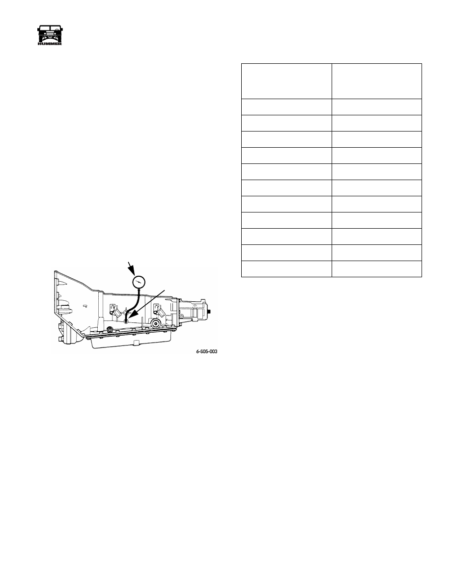
Connect pressure gauge to transmission test port
(Figure 5-16). Gauge must have 325-350 psi (2240-2413
kPa) capacity.
4.
Start engine and check pressures in Park, Neutral and both
Drive ranges. Pressure should be a minimum of 35 psi
(241 kPa) at idle and increase to a maximum of 171 psi
(1179 kPa) at greater throttle openings.
5.
Shift transmission into reverse and note pressure. At idle,
pressure should be a minimum of 67 psi (462 kPa) and
increase to a maximum of 324 psi (2234 kPa) as throttle
opening increases.
6.
Stop engine, remove gauge, and lower vehicle.
7.
If pressures were low in all ranges, pump may need repair
or replacement. Problem may be worn, damaged gears,
blown out cup plug, cross leakage, or worn bushing. If
pressure is high, fault may be with pressure control
solenoid, reverse/boost or pressure regulator valves, bad
PCM ground or solenoid connection.
Figure 5-16: Pressure Gauge
Pressure Control Solenoid Test
1.
Connect scan tool to diagnostic/data link connector.
2.
Connect pressure test gauge to transmission.
3.
Check fluid level and top off if necessary.
4.
Shift into Park and apply parking brakes.
5.
Start and operate engine at idle speed.
6.
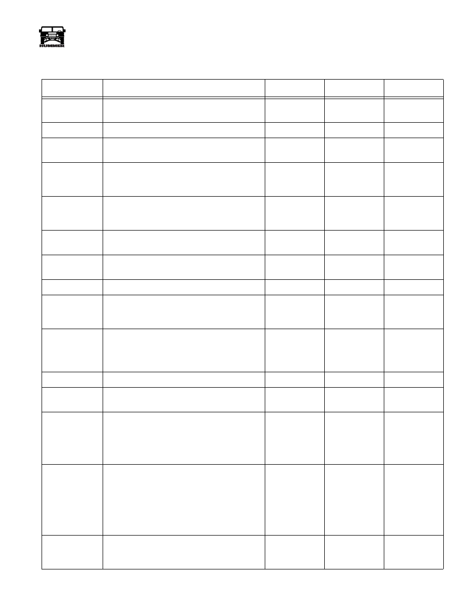
Access “override pressure control solenoid” test on scan
tool.
7.
Increase current to pressure control solenoid in amp
increments shown in chart (Figure 5-17), and record
pressure gauge readings. Allow gauge readings to stabilize
for 3-5 seconds after each current change.
8.
Stop engine and remove test tools.
9.
Compare test pressure readings with charge readings.
Pressures should decrease as current to solenoid is
increased. Consistently high pressures indicate a fault in
the PCM, related wiring, or solenoid. Low pressures
indicate an oil pump fault, or hydraulic circuit fault.
Figure 5-17: Pressure Control Solenoid Test
Specifications
RECOMMENDED FLUID
The recommended and preferred fluid for 4L80-E transmis-
sions is Dexron III.
In cases where Dexron III is not readily available, Dexron IIE
can be used to top off the fluid level. It is not, however, recom-
mended for use as the primary fluid for a fluid change.
Fluid Capacity
Fluid capacity of the 4L80-E used in Hummer vehicles is:
• Transmission refill capacity (after filter change) is ap-
proximately 7.7 qts. (7.3 L).
• Dry fill capacity (after overhaul) is approximately 13.5
qts (12.8 L)
• Cooler and line capacity is approximately 1-2 pts (.47-
.95 L)
NOTE:
Always fill transmission using the dipstick level as a
guide. Residual fluid left in the transmission during service
could result in an overfilled condition.
TRANSMISSION
TEST PORT
PRESSURE GAUGE
Amp Feed To Pressure
Control Solenoid (From
PCM)
Line Pressure - PSI (kPa)
0.0-0.02
157-177 (1083-1220)
0.10
151-176 (1041-1214)
0.20
140-172 (965-1186)
0.30
137-162 (945-1117)
0.40
121-147 (834-1014)
0.50
102-131 (703-903)
0.60
88-113 (607-779)
0.70
63-93 (434-641)
0.80
43-73 (296-503)
0.90
37-61 (255-421)
0.98-1.1
35-55 (241-379)

5-16
Transmission/Transfer Case
_____________________________________________
®
Fluid Level and Condition
Transmission fluid level and condition are important to proper
operation. An incorrect fluid level can lead to shift problems,
fluid breakdown, and accelerated wear.
Check fluid level and condition during the preliminary inspec-
tion procedure. This is important, as a low fluid level, or over-
fill condition can lead to slip and flare, overheating, burned
fluid, slow engagement, converter shudder, and no fourth gear
upshift.
An overfill condition allows the gear train to churn the fluid
into foam. this action aerates the fluid causing slip, overheat-
ing, oxidation, and overflow from the vent. A low level allows
the pump to take in air along with the fluid. Air in the fluid will
cause pressures to be low and develop slower than normal
shifts.
Checking Fluid Level
1.
Fluid must be at normal operating temperature. Drive
vehicle 10-15 miles (15-24 km) if necessary.
2.
Position vehicle on level surface.
3.
Operate engine at idle speed.
4.
Shift transmission into Park.
5.
Clean dipstick and top of fill tube with shop towel to avoid
dirt entry.
6.
Unlock and remove dipstick (Figure 5-19). Correct fluid
level is to hot full mark at top of crosshatch (Figure 5-18).
Adequate fluid level is anywhere in crosshatch area.
7.
Note color and condition of fluid. Refer to fluid condition
check.
8.
Add fluid only if level is below bottom mark of crosshatch
area. Add fluid in 1/4 to 1/2 pint/liter amounts to avoid
overfill. However, if overfill condition exists, drain
necessary amount of fluid with suction gun and length of
small plastic tubing. Or drain excess off at cooler line with
engine idling.
9.
Install and lock dipstick and shut engine off.
Figure 5-18: Transmission Fluid Level Marks
Figure 5-19: Releasing Transmission Dipstick Lock
Handle
OK
CROSSHATCH
AREA
HOT
FULL MARK
ADD FLUID WHEN
LEVEL IS BELOW
THIS MARK
FILL TUBE
TRANSMISSION
DIPSTICK AND
LOCK HANDLE
LIFT HANDLE
TO UNLOCK
FRONT
OF
VEHICLE
____________________________________________
Transmission/Transfer Case 5-17
®
05745159
Transmission Fluid Checking Procedure
Step
Action
Value(s)
Yes
No
1
Check the fluid color.
Is the fluid color red?
Go to step 2
Go to step 11
2
Is the fluid level satisfactory?
Go to step 21
Go to step 3
3
Check the fluid.
Is the fluid foamy?
Go to step 8
Go to step 4
4
Check the fluid level. The proper fluid level
should be in the middle fo the X-hatch.
Is the level high?
Go to step 9
Go to step 5
5
Fluid will be low.
Add fluid to the proper fluid level.
Is the fluid level satisfactory?
Go to step 6
6
Check for external leaks.
Did you find any leaks?
Go to step 7
Go to step 21
7
Correct the leak condition.
Did you correct the leak condition?
Go to step 21
8
Is the fluid level too high?
Go to step 9
Go to step 10
9
Remove excess fluid to the proper level. Refer to
Fluid Changing Proceedure.
Is the fluid level satisfactory?
Go to step 21
10
Check for contaminants in the fluid.
Drain the fluid to determine the source of the con-
tamination.
Did you drain the fluid?
Go to step 15
11
Is the fluid color an opaque pink?
Go to step 12
Go to step13
12
Repair the transmission vent line.
Is teh repair complete
Go to step 15
13
The fluid color should be light brown. Transmis-
sion fluid may turn dark with normal use. This
does not always indicate oxidation or contamina-
tion.
Is the fluid color light brown?
Go to step 14
14
Drain the fluid to determine if the fluid is contam-
inated.
A very small amount of material in the bottom
pan is a normal condition, but large pieces of
metal or other material in the bottom pan require
a transmission replacement.
Was the fluid contaminated?
Go to step 15
Go to step 18
15
Replace the transmission. Refer to transmission
replacement proceedures.
Is the replacement complete?
Go to step 16
5-18
Transmission/Transfer Case
_____________________________________________
®
SCAN TOOL DIAGNOSIS
NOTE:
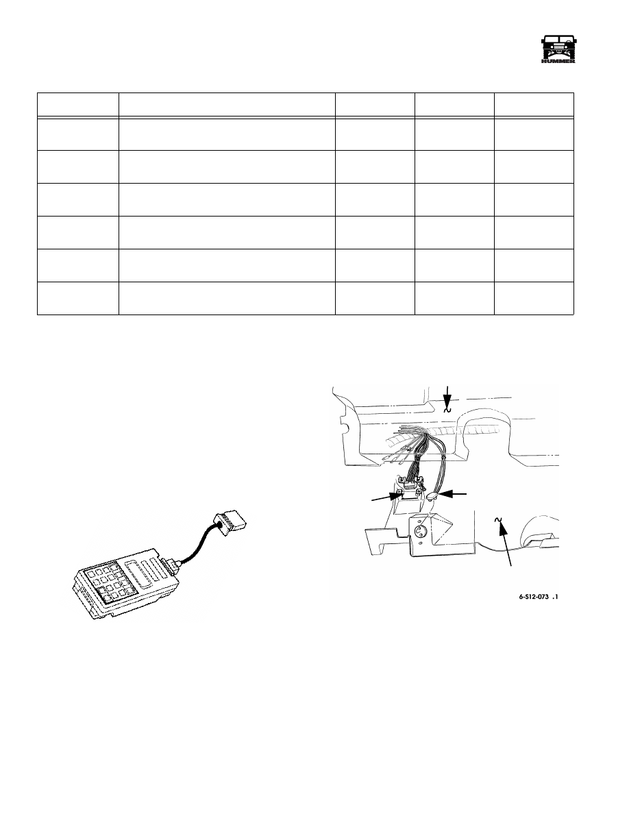
The Tech 1 Scan Tool (Figure 5-20) checks function of
the solenoids, sensors, and PCM. The scan tool connector is
attached to the vehicle data link connector (Figure 5-21).The
vehicle requires use of a VIM (Vehicle Interface Mod ule), part
number 7000041.
The scan tool provides data on individual circuits, or on all the
related electrical components in snap shot mode.
The PCM memory and circuits are interrogated by the scan tool.
The tool reads diagnostic trouble codes (DTC) and displays fault
and performance parameters.
Figure 5-20: Tech 1 Scan Tool
Figure 5-21: Data Link Connector
Transmission Warning Lamps
All Hummer vehicles are equipped with a malfunction indica-
tor light (check engine) and a check throttle light. The purpose
of the lights is to alert the driver when a transmission/engine,
or electronic accelerator pedal circuit fault has occurred.
The warning lights are in circuit with the PCM, which controls
light operation. The lights are illuminated for a few seconds at
startup as part of a bulb check and circuit self test routine. The
only other time illumination occurs, is when a system compo-
nent or circuit fault occurs.
16
Clear TRANS ADAPT.
Is the proceedure complete?
Go to step 17
17
Add new fluid.
Is the proceedure complete?
Go to step 20
18
Change the fluid and the filter.
Is the procedure complete?
Go to step 10
19
Clear TRANS ADAPT.
Is the procedure complete?
Go to step 20
20
Is the fluid level satisfactory? If not, correct as
needed.
Go to step 21
21
Perform the Functional Test Procedure.
Is the functional test completed?
System is OK
Transmission Fluid Checking Procedure
Step
Action
Value(s)
Yes
No
S05-008
DATA LINK
CONNECTOR
I.P.
I.P. CLOSEOUT PANEL
(SHOWN DETACHED)
COURTESY LIGHT
HARNESS
Нет комментариевНе стесняйтесь поделиться с нами вашим ценным мнением.
Текст