Hummer H1 (2002+). Manual — part 53
____________________________________________
Transmission/Transfer Case 5-11
®
05745159
TRANSMISSION SERVICEABILITY
The Hydra-matic transmission used in Hummer vehicles is ser-
viced at two levels. Only external parts are serviced during the
warranty period. A transmission internal component failure
will require transmission replacement. Service replacement
transmissions are available through the DCS.
External repairs include replacement of the following:
• oil pan, gasket, magnet and filter
• converter housing access covers
• shift solenoids
• pressure switch
• speed sensors
• pressure control solenoid
• converter clutch solenoid
• park lock detent, actuator, pawl, pin, spring shift, plug,
and bracket
• torque converter and seal
• fill tube, seal, and dipstick
• adapter and gasket
• rear mount insulator and bracket
• transmission wiring harness
• vent lines and cooler lines
• PCM
TRANSMISSION DIAGNOSIS
Transmission diagnosis is a three step procedure. The first step
involves two preliminary inspection procedures to check exter-
nal parts. The second step involves road testing to confirm and
identify a problem. The third step involves shop testing to lo-
cate the problem system or part. Shop testing includes pressure
testing, scan tool diagnosis, and visual inspection.
Preliminary Inspection - Vehicle is Driveable
1.
If problem involves vibration or noise, check following:
• tires and wheels for wear or damage
• drive belt and accessories for wear, or being loose
• propeller shaft U-joints for wear or damage
• exhaust pipes, muffler, converter touching body or
frame
• engine/transmission mount wear or damage
2.
Check transmission fluid condition as follows:
a.
Refer to Transmission Fluid Checking Procedure
3.
Check transmission fluid level as follows:
a.
Transmission fluid should be at normal operating
temperature for accurate check. Drive vehicle if
necessary.
b.
Start engine, apply brakes, shift through all gear
ranges and back to Park. Run engine at curb idle
speed.
c.
Remove dipstick and check fluid level. Fluid should
be in crosshatch area of dipstick.
d.
If level is low, add fluid in 1/4 pint/liter increments if
necessary. If fluid level is high, draw-off excess with
suction gun and plastic tubing inserted in filler tube.
CAUTION:
Do not overfill the transmission. Excess fluid will
be churned into foam aerating the fluid. The result will be fluid
overheat, shift problems and clutch wear.
4.
If fluid level was low, check for leaks at the oil pump seal,
cooler and lines, filler tube and oil pan.
5.
Check shift linkage adjustment. If vehicle starts only in
Park and Neutral, linkage is OK. Linkage needs
adjustment when engine won’t start in one of the ranges,
or if shift indicator in bezel is seriously misaligned.
6.
Inspect transmission harness and case connector. Repair
loose connections or damaged wiring as needed and
proceed to next step.
7.
If leaks, linkage, or fluid problems are not encountered,
proceed to road test.
Preliminary Inspection - Vehicle Is Disabled
1.
Check fluid level and condition as described in procedure
for driveable vehicles.
2.
Check for fluid leaks or broken shift linkage.
3.
Check driveline as follows: Raise vehicle so wheels are
free to rotate. Then start engine, shift transmission and
transfer case into gear, and note the following:
a.
If one or both propeller shafts turn but wheels do not,
problem is with differential or axle shafts.
b.
If propeller shafts turn but transmission or transfer
case is noisy, stop engine immediately. Then repair
transmission or transfer case as needed.
c.
If propeller shafts do not rotate and transmission is
not noisy, test transmission line pressure as described
in this section.
5-12
Transmission/Transfer Case
_____________________________________________
®
Road Test
1.
If engine and transmission have cooled down, drive vehi-
cle 10-12 miles to return to normal operating temperature.
NOTE:
The engine coolant and transmission fluid tempera-
tures must be at normal operating levels for a proper road test.
The engine and transmission temperature sensors will inhibit
upshifts otherwise.
2.
Check torque converter operation as follows:
a.
Operate vehicle at 50-55 mph (80-88 km/h).
b.
Lightly apply brakes and check for converter clutch
release. Engine rpm will increase slightly when
release occurs.
c.
Release brakes, accelerate again, and check for
converter clutch apply. Engine rpm will fall off
slightly when apply takes place.
d.
If shudder occurs during converter clutch apply, or
clutch won’t release, problem is with one of the
converter control valves, solenoid, or fluid level is
low. If shudder occurs after clutch apply, problem is
with engine, mounts, or other driveline component.
e.
If more than normal throttle opening is required to
accelerate and maintain cruise speed, stator roller
clutch may have failed.
3.
Check shifting in both D ranges. Verify 1-2 and 2-3
upshifts and 3-4 upshift in overdrive D range. Then
manually shift into 2 position at 25 mph. Transmission
should immediately shift into second gear but not upshift
to third. Stop vehicle and shift into 1 range. Accelerate to
25-30 mph and note operation. Transmission should
remain in first gear, provide overrun braking effect at
decel, and not upshift. Stop vehicle, shift into reverse and
backup. Vehicle should move smoothly in reverse. Check
kickdown operation in both D ranges. Transmission
should downshift promptly when accelerator pedal is
moved to wide open position.
4.
Drive vehicle in all gear ranges. The following indicate
transmission mechanical or electrical fault:
• loss of one or more gear ranges
• engine flare during shifts (indicates clutch slip)
• rough-harsh shifts
• noise in one or more gear ranges
• delayed or harsh engagement in D or R
• shudder or surge during shifts
• engine starts in range other than P or N
• engine stalls after shift to D
• loss of drive or reverse
Road Test Analysis
Shift problems such as harsh, or late shifts, indicate a problem
with the wiring, a sensor, low fluid level, or a PCM fault. Com-
plete loss of a gear range when the fluid is cold or hot, indi-
cates failure of a drive element.
An important diagnostic tool is the Transmission Elements In
Use chart (Figure 5-15). The chart indicates what elements are
applied, holding, or overrunning in each gear range. The chart
also indicates shift solenoid status in each gear range as well.
By comparing elements in use to a problem gear range, the
number of parts to be checked can be narrowed considerably.
In cases where loss of drive, slow engagement, or engine flare
are experienced, a line pressure test is needed. This test checks
oil pump and pressure control solenoid output and condition.
A torque converter fault will require scan tool testing to deter-
mine the problem part. A fault in one of the sensors or sole-
noids will also require scan tool testing. Incorrect shift points,
no 3-4 upshift, converter shudder or slip, and harsh engage-
ment are some of the problems caused by sensor, solenoid, wir-
ing, or a PCM fault. Potential causes for common shift
problems are described in the diagnosis guides. Corrective ac-
tion is also provided. Problem causes are listed in order of
probability (most-least).
____________________________________________
Transmission/Transfer Case 5-13
®
05745159
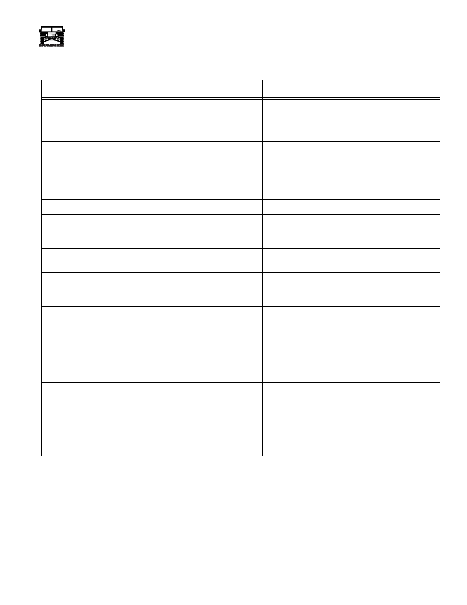
Functional Test Procedure
Step
Action
Value(s)
Yes
No
1
Perform the Transmission Fluid Checking Proce-
dure.
Fill the reservoir to the suggested level.
Is the fluid level correct?
Go to step 2
2
Check for PCM trouble codes, both current and
history.
Are PCM trouble codes present?
Go to the Diag-
nostic Trouble
Code Charts
Go to step 3
3
Perform the Road Test Procedure.
Was the condition Duplicated?
Go to step 4
Go to step 12
4
Is a harsh or soft shift condition present?
Go to step 7
Go to step 5
5
Is the vehicle’s performance poor?
Go to Torque
converter Clutch
Diagnosis
Go to step 6
6
Is the engagement into Drive or Reverse delayed
or missing?
Go to step 7
Go to step 9
7
Perform the Line Pressure Checking Procedure.
Is the line pressure correct?
Go to step 8
Refer to symp-
tom Diagnosis
Tables
8
Inspect the transmission wire harness connectors
and the transmission range switch.
Was the problem found and corrected?
System OK
Refer to symp-
tom Diagnosis
Tables
9
Is vibration or noise a concern?
Refer to Fly-
wheel/Torque
Converter
Vibration test
Go to step 10
10
Is the fluid leaking?
Locate and
repair leak
Go to step 11
11
Are other transmission conditions present?
Refer to Symp-
tom Diagnosis
Tables
Go to Step 12
12
Was the condition corrected?
Exit Table
Go to step 1

5-14
Transmission/Transfer Case
_____________________________________________
®
Figure 5-15: Transmission Elements In Use Chart
Clutch Application Chart
GEAR
1-2
SHIFT
SOLE-
NOID A
2-3
SHIFT
SOLE-
NOID B
FOURTH
CLUTCH
OVER-
RUN
CLUTCH
OVER-
DRIVE
ROLLER
CLUTCH
FOR-
WARD
CLUTCH
DIRECT
BAND
FRONT
BAND
INTER-
MEDIATE
SPRAG
CLUTCH
INTER-
MEDIATE
CLUTCH
LO
ROLLER
CLUTCH
REAR
BAND
P-N
ON
OFF
Holding
R
Rev.
ON
OFF
Holding
Applied
Applied
O
D
1st
ON
OFF
Holding Applied
*
Hold-
ing
2nd
OFF
OFF
Holding Applied
Holding
Applied Over-
running
3rd
OFF
ON
Holding Applied
Applied
Over-
running
Applied Over-
running
4th
ON
ON
Applied
Over-
running
Applied
Applied
Over-
running
Applied Over-
running
D
1st
ON
OFF
Applied
Applied Applied
*
Hold-
ing
2nd
OFF
OFF
Applied
Applied Applied
Holding
Applied Over-
running
3rd
OFF
ON
Applied
Applied Applied
Applied
Over-
running
Applied Over-
running
2
1st
ON
OFF
Applied
Applied Applied
*
Hold-
ing
2nd
OFF
OFF
Applied
Applied Applied
Applied Holding
Applied Over-
running
1
1st
ON
OFF
Applied
Applied Applied
*
Hold-
ing
Applied
* Holding, but not effective • Solenoid operation follows a shift pattern dependent on vehicle
speed and throttle position and not gear range.
ON = Solenoid energized
OFF = Solenoid de-energized
Нет комментариевНе стесняйтесь поделиться с нами вашим ценным мнением.
Текст