Hummer H1 (2002+). Manual — part 47
___________________________________________________________
Cooling System 4-3
®
05745159
quicker. At high temperatures, fluid viscosity decreases and
more fluid circulates through the cooler maintaining an even
operating temperature and a constant pressure in the cooler
(see Section 1 for service procedures).
A separate smaller oil cooler, mounted to the fan shroud, is
used to cool the power steering fluid.
Two fluid returns are used: one from the hydro-boost and one
from the power steering gear. Fluid flow through the hydro-
boost is never completely restricted during braking. The hydro-
boost incorporates a fluid return to release the hydraulic pres-
sures used when applying the brakes (see Section 8 for service
procedures).
ENGINE COOLING SYSTEM DIAGNOSIS AND
TROUBLESHOOTING
WARNING: Do not release surge tank cap when en-
gine is hot. Steam and/or coolant may cause serious in-
jury.
Loss of Coolant
1.
Pressurize system and check for leaks at all cooling sys-
tem hoses.
a.
Tighten loose clamps, fasteners, or fittings.
b.
Replace leaking hoses.
2.
Pressurize coolant system and check for leaks at water
pump or around cylinder heads. If any leakage is present,
replace cylinder head gaskets, cylinder heads, or water
pump.
3.
Check cylinder block for cracks. Replace if cylinder block
is cracked.
4.
Check expansion plugs and block heater for leaks.
5.
Check radiator and surge tank.
6.
Remove surge tank cap. With engine running, check for
excessive bubbles in surge tank that may indicate leaking
head gaskets or cracked cylinder heads. If bubbles are
present, remove cylinder heads and check for defective
head gaskets, cracked cylinder heads, or cracked cylinder
block. Replace cylinder heads if damaged. Replace engine
if cylinder block is cracked.
Engine Coolant Temperature Gauge Above
255°F (124°C), Engine Overheats
1.
Inspect for low coolant. Verify low coolant sensor is oper-
ating properly. (Refer to Electrical Troubleshooting, Sec-
tion 12).
2.
Inspect the drivebelt and pulleys for damage.
a. Replace any damaged parts.
b. Check belt tension. Replace if necessary.
WARNING: Use caution when testing thermostat. Hot
engine coolant will cause burns.
NOTE
: Off-road driving in extremely dusty conditions may
result in debris entrapment between the radiator and oil cooler.
Trapped debris may increase coolant temperature.
3.
Check for clogged or blocked radiator system. Clean and
flush as required. Cleaning requires the separation of the
oil cooler from the radiator and both units must be
thoroughly flushed with water and compressed air.
4.
Check thermostat for proper operation. Remove
thermostat and place thermostat in container of water
known to be 190°F (88°C). Observe valve. If valve does
not open, replace thermostat.
5.
Check radiator for bent fins. Straighten fins or replace
radiator if damaged beyond repair.
6.
Check operation of temperature gauge. Refer to Electrical
Troubleshooting (Section 12).
7.
Inspect fan blades for damage. Replace fan if damaged.
8.
Check fan clutch operation.
a.
Check for excessive bearing play. Using fingers only,
press tip of fan blade toward and away from engine.
Tip of blade total movement should not exceed 0.20
in. (5.1 mm). If movement is more, replace fan drive.
b.
With engine off and ambient temperature of 50°F (10°
C) or higher, fan should turn evenly with noticeable
drag. If fan turns hard, very easily, or with uneven
resistance, replace fan drive.
c.
Fan noise is sometimes evident under the following
normal conditions:
• When the drive is engaged for maximum cooling.
• During the first 15 seconds to one minute after start-
up, until the drive can redistribute the silicone fluid
back to its normal disengage operating condition
(after overnight settling).
Fan noise or an excessive roar will generally occur
continuously under all engine high speed conditions
(2400 RPM and up) if the drive assembly is locked-up
due to an internal failure. If the fan cannot be rotated
by hand or there is a rough, grating feel as the fan is
turned, replace the fan drive.
9.
Check for leaking or defective water pump. Replace
leaking or defective water pump.
WARNING: Do not release surge tank cap when engine
is hot. Steam and/or coolant may cause serious injury.
Fan Runs Continuously (Noisy)
1.
Check that all fan bolts are present and tightened to 45 lb-
ft (61 N•m).
2.
Perform steps 8a and 8b on preceding page.
3.
Check for fan cut off (disengagement).
4.
Observe fan drive disengagement after 1 to 1-1/2 minutes.
If fan speed does not drop and coolant temperature
remains below 190° F (88° C), replace fan drive.
4-4
Cooling System
____________________________________________________________
®
RADIATOR AND FAN SHROUD ASSEMBLY
SERVICE
Removal
1.
Remove hood (Section 10).
2.
Drain cooling system.
3.
Remove oil cooler (Section 1).
4.
Disconnect upper hose from radiator (Figure 4-4).
5.
If equipped with air conditioner, discharge system and
remove condenser (Section 11).
6.
Remove power steering cooler mounting bolts and
position cooler aside.
7.
Disconnect ambient temperature switch, if equipped
(Section 11).
8.
Disconnect surge tank-to-radiator vent hose from adapter.
9.
Disconnect lower radiator hose from radiator.
10. Remove strap securing fan shroud to radiator.
11. Remove lower mount from radiator and frame bracket
(Figure 4-5).
12. Detach rear support brackets from airlift brackets
(Figure 4-4).
13. Remove battery tray, and left splash shield. (Sections 10
and 12).
14. Remove the radiator from vehicle (Figure 4-5).
15. Remove retaining strips, and fan shroud from radiator.
16. Remove rear support brackets and insulators from
radiator.
Cleaning and Inspection
NOTE:
Clean all components, examine for wear or damage,
and replace if necessary.
1.
Remove debris embedded in radiator fins using water and
compressed air (Figure 4-5).
2.
Inspect radiator for breaks, punctures, cracks, or splits.
3.
Inspect adapters and fan shroud (Figure 4-4).
Installation
CAUTION:
To avoid equipment damage, upper edge of fan
shroud must align with radiator top tank seam to ensure
proper engine cooling.
NOTE:
Ensure fan shroud edge aligns with tank seam on radi-
ator.
1.
Secure fan shroud to radiator with retaining strips, lock-
washers, and bolts. Tighten bolts to 6 lb-ft (8 N•m)
(Figure 4-5).
2.
Secure rear support brackets and insulators to radiator
with washers and locknuts. Tighten locknuts to 26 lb-ft
(35 N•m).
3.
Align radiator with frame bracket, and rear support
brackets with airlift brackets (Figures 4-5 and 4-6).
4.
Fasten rear support brackets to air lift brackets with bolts,
washers, and locknuts. Do not tighten locknuts
(Figure 4-4).
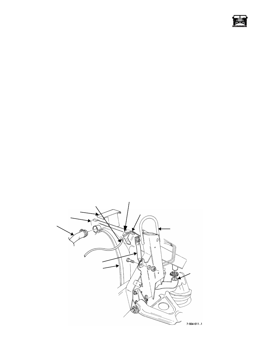
Figure 4-4: Radiator and Fan Shroud Assembly Mounting
RADIATOR
UPPER RADIATOR HOSE
REAR SUPPORT BRACKET
LOWER RADIATOR HOSE
AIRLIFT BRACKET
ADAPTER
SURGE TANK-TO-RADIATOR VENT HOSE
FAN SHROUD
STRAP
HOSE FITTING WITH BLEED VALVE
___________________________________________________________
Cooling System 4-5
®
05745159
5.
Attach lower mount and radiator to frame bracket with
washers, and locknut. Do not tighten (Figure 4-5).
6.
Align fan shroud by sliding the radiator/shroud
assembly to maintain 1 1/2 ± 1/8 in. (38.1 ± 3 mm) from
edge of shroud ring and rear edge of fan. Measure at the
2, 4, 8, and 10 o’clock positions. The distance between
the top of the fan blade and fan shroud must not be less
than 1/4 in. (6 mm) at any position (Figure 4-6).
7.
Tighten rear support bracket locknuts to 26 lb-ft (35 N•m).
Tighten frame bracket bolt to 30 lb-ft (41 N•m)
(Figures 4-4 and 4-5).
8.
Install left splash shield and battery tray (Section 12).
9.
Install strap on radiator and shroud (Figure 4-4).
10. Connect upper and lower radiator hoses to radiator.
11. Use bolts to attach power steering cooler to brackets.
12. Connect ambient temperature switch, if equipped
(Section 11).
13. If equipped with air conditioner, install condenser and
charge system (Section 11).
14. Connect surge tank-to-radiator vent hose to adapter.
15. Fill cooling system (Section 4).
16. Install oil cooler (Section 1).
17. Start engine and check cooling system for leaks.
18. Install hood (Section 10).
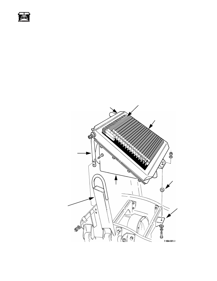
Figure 4-5: Radiator and Fan Shroud Assembly Breakdown
RADIATOR
LOWER
MOUNT
FRAME
BRACKET
FAN SHROUD
REAR SUPPORT BRACKET
OIL COOLERS
CONDENSER
RIGHT SIDE
AIR LIFT BRACKET

4-6
Cooling System
____________________________________________________________
®
ENGINE COOLING SYSTEM SERVICE
Depressurizing/Draining
WARNING: To avoid injury, do not remove surge tank
filler cap before depressurizing cooling system when
engine temperature is above 190°F (88°C).
1.
If engine is hot, place a thick cloth over surge tank filler
cap. Turn counterclockwise to first stop to release internal
pressure (Figure 4-8).
2.
After pressure has vented, remove cap.
3.
Open drain valve and drain system (Figure 4-7).
4.
Close drain valve.
Replenishing
NOTE:
Ensure surge tank coolant level is 3/4 full before se-
curing filler cap.
1.
Ensure drain valve is closed and heater control valve is
open (Figure 4-7).
2.
Fill system with proper antifreeze solution (Table 4-1).
3.
Install filler cap on surge tank (Figure 4-8).
4.
Start engine and run at fast idle (1500 rpm) until engine
temperature reaches 190° F (88° C). Stop engine.
5.
Depressurize system.
6.
Fill with proper antifreeze solution until surge tank is 3/4
full (Table 4-1).
7.
Install filler cap on surge tank (Figure 4-8).
8.
Start engine and run at fast idle (1500 RPM) until engine
temperature reaches 190° F (88° C). Stop engine.
9.
Depressurize system. Use tester to ensure proper coolant
protection is provided.
10. Install filler cap on surge tank.
11. Start engine and check cooling system for leaks.
Figure 4-6: Fan Shroud Clearance Check Points
Figure 4-7: Drain Valve
Figure 4-8: Surge Tank and Filler Cap Location
10 O’CLOCK
2 O’CLOCK
8 O’CLOCK
4 O’CLOCK
FAN
SHROUD
POSITION
POSITION
POSITION
POSITION
DRAIN VALVE
SURGE TANK
FILLER CAP
SURGE
TANK
Expected Ambient
Temperature
Antifreeze/
Water Mixture
120° to -32° F
(49° to -36° C)
50% antifreeze/
50% water
Table 4-1: Antifreeze Preparation Guide
Нет комментариевНе стесняйтесь поделиться с нами вашим ценным мнением.
Текст