Hummer H1 (2002+). Manual — part 148

________________________________________
Axles, Suspension, and Frame 9-53
®
05745159
SPRING SEAT REPLACEMENT
NOTE:
Replacement of the four spring seats is basically the
same. This procedure covers the right front spring seat.
Removal
1.
Remove coil spring.
2.
Remove four locknuts, washers, bolts, spring bracket, and
front spring seat from frame rail (Figure 9-127).
Installation
1.
Install spring bracket and front spring seat on frame rail
with four washers, bolts, washers, and locknuts. Tighten
locknuts to 261 lb-ft (354 N•m) (Figure 9-127).
2.
Install coil spring.
Figure 9-127: Front Spring Seat Replacement
REAR BUMPER OUTER MOUNTING BRACKET
AND TIEDOWN BRACKET REPLACEMENT
Removal
1.
Remove rear body mount (Section 10).
2.
Remove two locknuts, washers, bolts, and washers
securing tiedown bracket and outer mounting bracket to
mounting bracket and rear bumper (Figure 9-128).
3.
Remove two bolts and washers securing outer mounting
bracket to mounting bracket.
4.
Remove four locknuts, washers, bolts, washers, outer
mounting bracket, and spacer from frame rail and inner
mounting bracket.
Installation
NOTE:
Ensure spacer on inner side of frame rail is in position
before installing spacer and outer mounting bracket.
1.
Install spacer and outer mounting bracket on frame rail and
inner mounting bracket with four washers, bolts, washers,
and locknuts. Do not tighten locknuts (Figure 9-128).
2.
Secure outer mounting bracket to mounting bracket with
two washers and bolts. Do not tighten bolts.
3.
Install tiedown bracket on rear bumper and secure tiedown
bracket and outer mounting bracket to mounting bracket
and rear bumper with two washers, bolts, washers, and
locknuts.
4.
Tighten all locknuts and bolts to 90 lb-ft (122 N•m).
5.
Install rear body mount (Section 10).
Figure 9-128: Rear Bumper Mounting Bracket
Replacement
SPRING BRACKET
FRAME RAIL
FRONT SPRING SEAT
MOUNTING
BRACKET
FRAME
RAIL
TIEDOWN BRACKET
REAR
SPACER
BUMPER
OUTER MOUNTING
BRACKET

9-54
Axles, Suspension, and Frame
_________________________________________
®
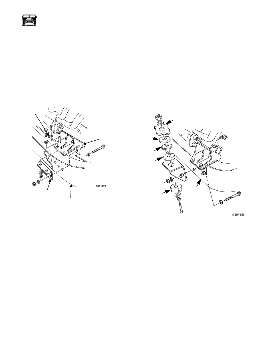
LEFT ENGINE MOUNT BRACKET REPLACEMENT
Removal
1.
Remove two bolts securing brake line and oil line clamps
to engine mount bracket (Figure 9-129).
2.
Remove two locknuts and washers securing engine mount
bracket to insulator.
CAUTION: To avoid engine oil pan damage, wood block must
completely cover bottom of oil pan.
3.
Support engine under engine oil pan with wood block and
jack stand (Figure 9-130).
4.
Remove four locknuts, washers, bolts, washers, and
engine mount bracket from frame rail (Figure 9-129).
Figure 9-129: Left Engine Mount Bracket
Replacement
Installation
1.
Install engine mount bracket on frame rail with four wash-
ers, bolts, washers, and locknuts. Tighten locknuts to 90
lb-ft (122 N•m) (Figure 9-129).
2.
Remove wood block and jack stand from under engine oil
pan (Figure 9-130).
3.
Secure engine mount bracket to insulator with two
washers and locknuts. Tighten locknuts to 90 lb-ft (122
N•m) (Figure 9-129).
4.
Secure brake line and oil line clamps to engine mount
bracket with two bolts.
Figure 9-130: Supporting Engine
BRAKE
OIL LINE CLAMP
INSULATOR
ENGINE MOUNT
BRACKET
FRAME RAIL
LINE CLAMP
ENGINE
WOOD BLOCK
JACK STAND
OIL PAN
________________________________________
Axles, Suspension, and Frame 9-55
®
05745159
RIGHT ENGINE MOUNT BRACKET
REPLACEMENT
Removal
1.
Remove right engine mount and insulator (Section 2).
2.
Remove two locknuts, washers, bolts, and washers
securing support bracket to engine mount bracket
(Figure 9-131).
3.
Remove bolt securing vent tube clamp to engine mount
bracket.
4.
Remove three locknuts, washers, bolts, washers, support
bracket, and engine mount bracket from frame rail.
Figure 9-131: Right Engine Mount Bracket
Replacement
Installation
1.
Install support bracket and engine mount bracket on frame
rail with three washers, bolts, washers, and locknuts
(Figure 9-131).
2.
Install support bracket on engine mount bracket with two
washers, bolts, washers, and locknuts. Tighten locknuts to
90 lb-ft (122 N•m).
3.
Install vent tube clamp on engine mount bracket with bolt.
4.
Install right engine mount and insulator (Section 2).
RIGHT FRONT BODY MOUNT BRACKET
REPLACEMENT
Removal
1.
Remove right front body mount.
2.
Remove three locknuts, washers, bolts, washers, and right
front body mount bracket from frame rail (Figure 9-132).
Installation
1.
Install right front body mount bracket on frame rail with
three washers, bolts, washers, and locknuts. Tighten lock-
nuts to 90 lb-ft (122 N•m) (Figure 9-132).
2.
Install right front body mount (Section 10).
Figure 9-132: Right Front Body Mount Bracket
Replacement
VENT TUBE
CLAMP
FRAME RAIL
SUPPORT
ENGINE MOUNT
BRACKET
BRACKET
FRAME
RAIL
LOWER
CUSHION
UPPER
CUSHION
SLEEVE
SPACER
BODY

9-56
Axles, Suspension, and Frame
_________________________________________
®
TRANSMISSION MOUNT CROSSMEMBER
REPLACEMENT
Removal
CAUTION: To prevent equipment damage during removal and
installation of transmission mount crossmember, transmission
must be supported.
1.
Place support under transmission and remove two lock-
nuts, washers, bolts, and washers securing transmission
mount crossmember to two transmission support brackets
(Figure 9-133).
2.
Remove two locknuts, washers, and transmission mount
crossmember from transmission mount.
Installation
1.
Install transmission mount crossmember on two transmis-
sion support brackets with two washers, bolts, washers,
and locknuts. Tighten locknuts to 90 lb-ft (122 N•m)
(Figure 9-133).
2.
Install crossmember on transmission mount with two
washers and locknuts. Tighten locknuts to 28 lb-ft
(38 N•m).
3.
Remove support.
Figure 9-133: Transmission Mount Crossmember
Replacement
TRANSMISSION CROSSMEMBER SUPPORT
BRACKET REPLACEMENT
Removal
1.
Remove transmission mount crossmember.
2.
Remove two locknuts and washers securing transmission
crossmember support bracket to frame rail (Figure 9-134).
Installation
1.
Install transmission crossmember support bracket on two
bolts and frame rail with two washers and locknuts.
Tighten locknuts to 90 lb-ft (122 N•m) (Figure 9-134).
2.
Install transmission mount crossmember.
Figure 9-134: Transmission Crossmember
Support Bracket Replacement
TRANSMISSION
SUPPORT
BRACKET
TRANSMISSION MOUNT
TRANSMISSION MOUNT
CROSSMEMBER
FRAME RAIL
TRANSMISSION
CROSSMEMBER
SUPPORT BRACKET
Нет комментариевНе стесняйтесь поделиться с нами вашим ценным мнением.
Текст