Hummer H1 (2002+). Manual — part 149
________________________________________
Axles, Suspension, and Frame 9-57
®
05745159
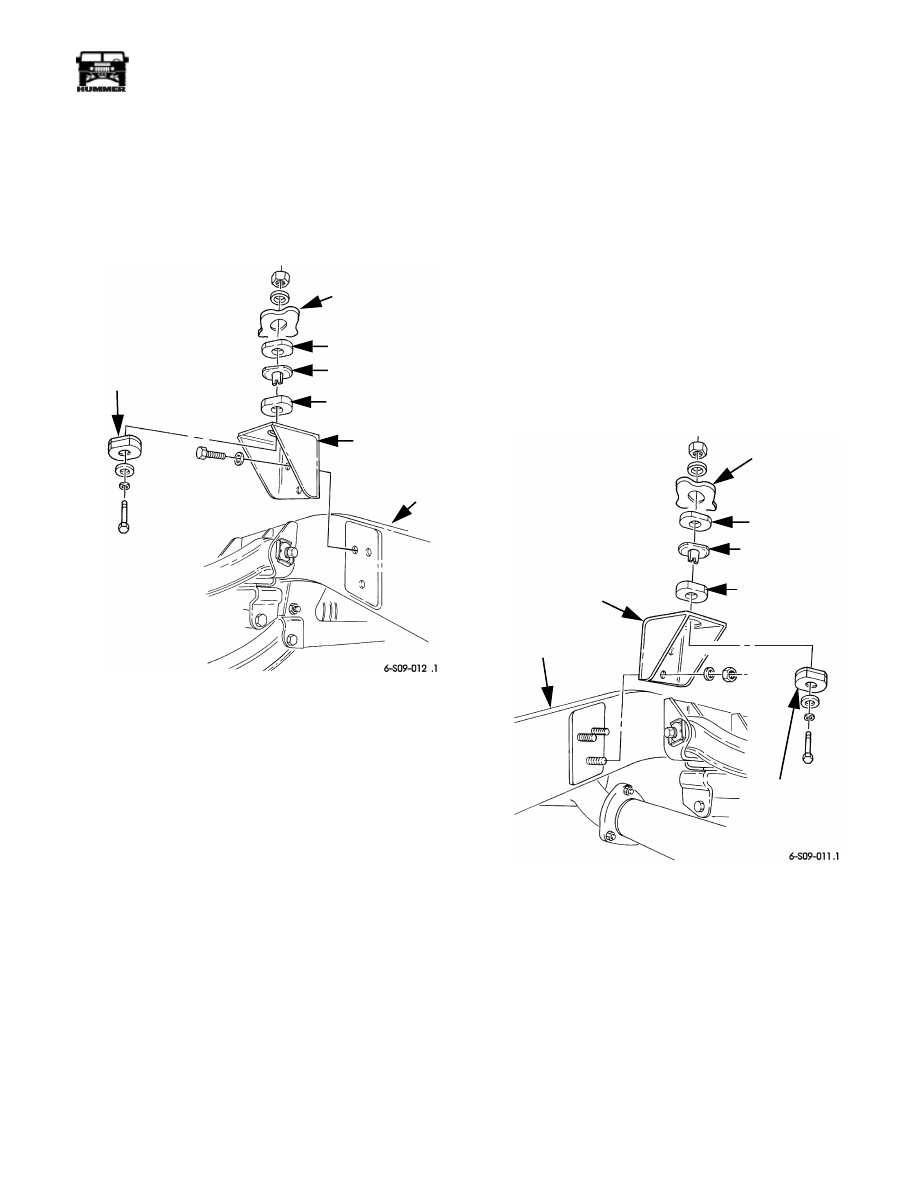
RIGHT INTERMEDIATE BODY MOUNT BRACKET
REPLACEMENT
Removal
1.
Remove right intermediate body mount (Section 10).
2.
Remove three bolts, washers, and body mount bracket
from frame rail (Figure 9-135).
Figure 9-135: Right Intermediate Body Mount
Bracket Replacement
Installation
1.
Apply thread-locking compound to three bolts and install
body mount bracket on frame rail with three washers and
bolts. Tighten bolts to 90 lb-ft (122 N•m) (Figure 9-135).
2.
Install right intermediate body mount (Section 10).
LEFT INTERMEDIATE BODY MOUNT BRACKET
REPLACEMENT
Removal
1.
Remove left intermediate body mount (Section 10).
2.
Remove tailpipe hanger (Section 11).
3.
Remove three locknuts, washers, and body mount bracket
from frame rail (Figure 9-136).
Installation
1.
Install body mount bracket on three bolts and frame rail
with three washers and locknuts. Tighten locknuts to 90 lb-
ft (122 N•m) (Figure 9-136).
2.
Install tailpipe hanger (Section 11).
3.
Install left intermediate body mount (Section 10).
Figure 9-136: Left Intermediate Body Mount Bracket
Replacement
BODY
SPACER
SLEEVE
UPPER
CUSHION
BODY
MOUNT
BRACKET
FRAME
RAIL
LOWER
CUSHION
BODY
SPACER
SLEEVE
UPPER
CUSHION
LOWER
CUSHION
FRAME
RAIL
BODY
MOUNT
BRACKET

9-58
Axles, Suspension, and Frame
_________________________________________
®
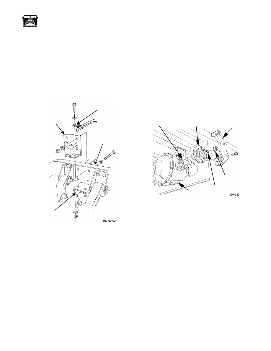
REAR-REAR TIEDOWN BRACKET
REPLACEMENT
Removal
Remove two locknuts, washers, bolts, washers, and tie-down
bracket from frame rail (Figure 9-137).
Installation
Install tiedown bracket on frame rail with two washers, bolts,
washers, and locknuts. Tighten locknuts to 261 lb-ft (354 N•m)
(Figure 9-137).
Figure 9-137: Tiedown Bracket Replacement
REAR UPPER CONTROL ARM BRACKET
REPLACEMENT
NOTE:
The procedure for removing and installing the four
rear upper control arm brackets is basically the same. This pro-
cedure covers the right rear upper control arm front bracket.
Removal
1.
Remove wheel.
2.
Remove bolt, clamp, and vent line from bracket, and
disconnect vent line from fitting
3.
Remove two locknuts, washers, bolts, washers, and upper
control arm from two control arm brackets (Figure 9-139).
4.
Remove four locknuts, washers, bolts, washers, vent line
mounting bracket, and control arm bracket from frame
rail.
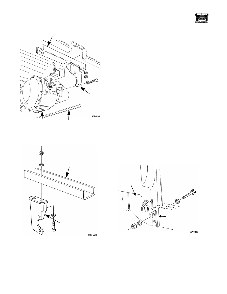
Figure 9-138: Rear geared Hub Vent Line Location
Installation
1.
Install control arm bracket, and vent line mounting bracket
on frame rail with four washers, bolts, washers, and locknuts.
Tighten locknuts to 172 lb-ft (233 N•m) (Figure 9-139).
2.
Attach upper control arm to two upper control arm
brackets with cam washers, bolts, washers, and locknuts.
Tighten locknuts to 260 lb-ft (353 N•m).
3.
Connect vent line to fitting and secure clamp and vent line
to bracket with bolt (Figure 9-138).
4.
Install wheel.
Figure 9-139: Rear Upper Control Arm Bracket
Replacement
TIEDOWN
FRAME RAIL
BRACKET
BRACKET
FITTING
GEARED HUB
VENT
LINE
VENT LINE
FRAME RAIL
CONTROL
UPPER CONTROL ARM
ARM
BRACKET
MOUNTING
BRACKET
________________________________________
Axles, Suspension, and Frame 9-59
®
05745159
REAR-FRONT TIEDOWN BRACKET
REPLACEMENT
Removal
1.
Remove wheel (Section 6).
2.
Remove four locknuts, washers, bolts, washers, and
tiedown bracket from frame rail (Figure 9-140).
3.
Remove two locknuts, washers, bolts, washers, vent tube/
speed sensor lead mounting bracket, and tiedown bracket
from rear suspension front crossmember mounting
bracket.
Figure 9-140: Rear-Front Tiedown Bracket
Replacement
Installation
1.
Install tiedown bracket and vent tube mounting bracket on
rear suspension front crossmember mounting bracket with
two washers, bolts, washers, and locknuts. Tighten lock-
nuts to 90 lb-ft (122 N•m) (Figure 9-140).
2.
Install tiedown bracket on frame rail with four washers,
bolts, washers, and locknuts. Tighten locknuts to 261 lb-ft
(354 N•m).
3.
Install wheel.
AXLE SUPPORT BRACKET AND SIDE
MOUNTING BRACKET REPLACEMENT
Removal
1.
Remove brake caliper and rotor.
2.
Remove locknut, seal washer, and output flange from
output shaft. Discard seal washer (Figure 9-141).
3.
Remove two bolts and brake adapter from axle.
4.
Remove two bolts and washers securing side mounting
bracket to axle (Figure 9-142).
5.
Remove two locknuts, washers, bolts, washers, support
bracket, and side mounting bracket from crossmember.
6.
Remove two locknuts, washers, bolts, washers, and side
mounting bracket from support bracket (Figure 9-143).
Figure 9-141: Brake Adapter and Output Flange
Replacement
Installation
1.
Install side mounting bracket on support bracket with two
washers, bolts, washers, and locknuts (Figure 9-143).
2.
Install support bracket and side mounting bracket on
crossmember with two washers, bolts, washers, and
locknuts (Figure 9-142). Do not tighten bolts.
3.
Apply thread-locking compound to tapped holes of axle
and install two washers, bolts, and side mounting bracket
on axle. Tighten side mounting bracket bolts to 110-139
lb-ft (149-189 N•m) and support bracket bolts to 90 lb-ft
(122 N•m).
4.
Apply thread-locking compound to tapped holes of axle
and install brake adapter on axle with two bolts. Tighten
bolts to 110-139 lb-ft (149-189 N•m) (Figure 9-141).
5.
Install output flange on output shaft with seal washer and
locknut. Tighten locknut to 170 lb-ft (231 N•m).
6.
Install brake caliper and rotor.
TIEDOWN BRACKET
FRAME RAIL
CROSSMEMBER
MOUNTING
BRACKET
VENT TUBE
SPEED SENSOR LEAD
BRACKET
OUTPUT SHAFT
OUTPUT FLANGE
BRAKE ADAPTER
SEAL WASHER
AXLE
LOCKNUT
9-60
Axles, Suspension, and Frame
_________________________________________
®
Figure 9-142: Side Mounting Bracket Removal
Figure 9-143: Support Bracket Replacement
FRONT SUSPENSION FRONT CROSSMEMBER
REPLACEMENT
Removal
1.
Remove front lower control arms.
2.
Remove lower radiator hose.
3.
Remove horn.
4.
Remove radiator front mounting bracket.
5.
Remove two nuts, washers, bolts, and washers securing
front crossmember to support bracket (Figure 9-142).
NOTE:
Note direction of bolts for installation.
6.
Remove four locknuts, washers, bolts, and washers
securing two splash shield brackets to frame rails
(Figure 9-144).
WARNING: To avoid personal injury, support cross-
member during removal.
7.
Remove bolt and clamp securing harness to front cross-
member (Figure 9-145).
8.
Remove four locknuts, washers, bolts, and washers
securing crossmember mounting brackets to frame rails.
9.
Slide crossmember and mounting brackets down and out
from under vehicle.
10. Remove six locknuts, washers, bolts, washers, and left and
right mounting brackets from crossmember.
Figure 9-144: Splash Shield Mounting
SUPPORT BRACKET
AXLE
CROSSMEMBER
SIDE
MOUNTING
BRACKET
SUPPORT BRACKET
SIDE MOUNTING BRACKET
FRAME RAIL
SPLASH SHIELD BRACKET
Нет комментариевНе стесняйтесь поделиться с нами вашим ценным мнением.
Текст