Hummer H1 (2002+). Manual — part 80
___________________________________________
Transmission/Transfer Case 5-119
®
05745159
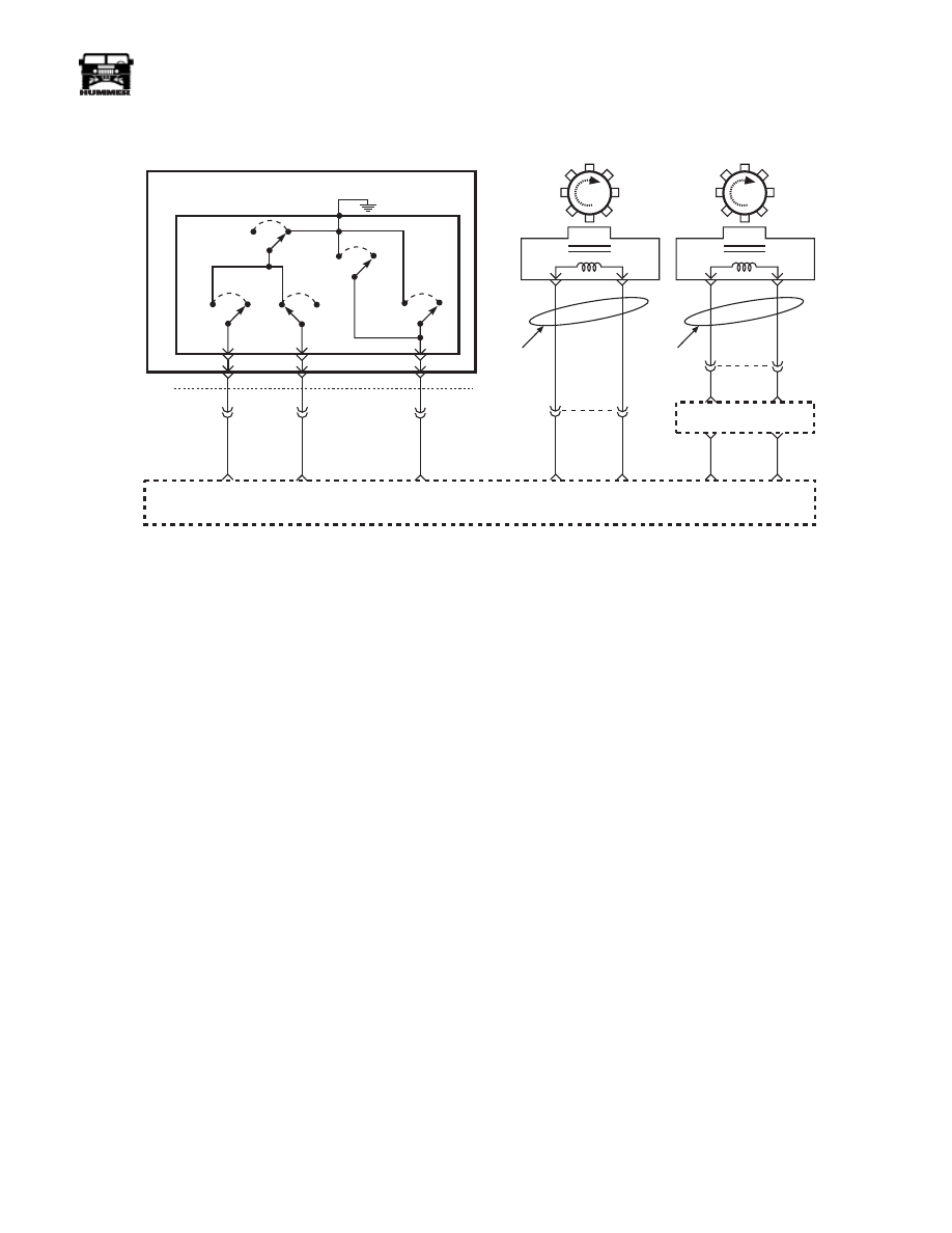
DTC P1871 Undefined Gear Ratio
Circuit Description
The PCM calculates ratio based on transmission input and out-
put speed sensor readings. The PCM compares known trans-
mission ratio to calculated ratio, for gear range selected.
This DTC detects an unknown ratio.
Conditions For Seating The DTC
The following conditions are met for 10 seconds.
• No DTCs P0121, P0122, P0123, P0220, P0221, P0222,
P0223, P0225, P0226, P0227, P0228.
• No DTCs P0716 or P0717.
• No DTCs P0722 or P0723.
• No DTCs P1810.
• No Four Wheel Drive Lo DTC P1875.
• Four Wheel Drive Lo fail counters are clear.
• Vehicle Speed is greater than 11 km/h (7 mph).
• Throttle angle is greater than 25%.
• Transmission fluid temperature is greater than 20°C
(68°F).
• 4.5 seconds since last gear change.
• Engine Speed is greater than 3650 rpm.
• Engine Torque is between 80 and 450 ft/ lbs.
• Gear Ratio is greater than 2.63 or less than 0.70
• Above conditions occur for 10 seconds.
Action Taken When The DTC Sets
• The PCM will command maximum line pressure.
• The PCM will freeze shift adapts.
Conditions For Clearing The MIL/DTC
• The PCM will turn the warning lamp off after three con-
secutive ignition cycles without a failure reported.
• The DTC can be cleared using the scan tool.
• The PCM will cancel the DTC default actions when a
fault no longer exists, and the ignition is cycled “Off”
long enough to power down the PCM.
Diagnostic Aids
• Inspect the wiring for poor electrical connection at the
PCM and the transmission 20-way connector.
• When diagnosing for a possible intermittent short or
open condition, move or wiggle the wiring harness
while observing test equipment for a change.
• If any engine DTC(s) or TP Sensor codes are present in
memory, diagnose and clear the engine DTC(s) first.
Then check to see if the transmission DTC(s) have reset.
Test Description
The numbers below refer to the diagnostic table.
1. This test checks indicated range signal to the actual
selected range. A faulty switch could set pressure
switch DTC P1870.
2. This test checks for proper ratios when in each com-
manded gear state.
TRANS
RANGE C
IINPUT
TRANS
RANGE B
INPUT
TRANS
RANGE A
INPUT
C34
P
R
N
D
E
C
REV
SWITCH
LO
SWITCH
D2
SWITCH
D3
SWITCH
D4
SWITCH
C32-S
C32-H
C32-K
764 PP
763 DB
762 OR
C29-B4
C29-B5
C29-B6
A / T ISS
HIGH
A / T ISS
LOW
B
C32-B
A
A
AUTO TRANS
INPUT SHAFT
SPEED SENSOR
A/T ISS
C27-D1
C27-D11
495 DB
496 GY
POWERTRAIN CONTROL MODULE (PCM)
9-S12-071.1
VSS
VSS
T W I S T E D
PA I R
B
A
TRANFER CASE
VEHICLE
SPEED
SENSOR
VSS
C29-A6
C29-A3
679 LG
676 PP
T W I S T E D
PA I R
DIGITAL RATIO ADAPTER
AUTOMATIC TRANSMISSION
FLUID PRESURE MANUAL VALVE POSITION SWITCH
(TFP)
223 DB
565 BR
C33-B
A

5-120
Transmission/Transfer Case
___________________________________________
®
DTC P1871 Undefined Gear Ratio
Step
Action
Value
Yes
No
1
Was the powertrain On-Board Diagnostic (OBD) Sys-
tem Check Performed?
—
Go To step 2
Go to Power-
train OBD
system Check
2
Perform the transmission fluid checking procedure.
Refer to Fluid Level and Condition.
Is the procedure complete?
—
Go to step 3
Go to Trans-
mission Fluid
Level and
Condition
3
1.
Install the scan tool.
2.
With the engine OFF, turn the ignition switch to
the RUN position.
NOTE: Before clearing the DTCs, use the scan
tool in order to record the Freeze Frame and
Failure Records for reference.
3.
Record the DTC Freeze Frame and Failure
Records.
4.
Record the DTCs.
5.
Start the engine.
6.
Apply the parking brake, and select each transmis-
sion range: D1, D2, D3, D4, N, R, and P.
Does the scan tool TFP switch A/B/C display match
each selected gear range?
—
Go to step 4
Refer to DTC
P1810 Pres-
sure Switch
Assembly
Malfunction,
in this section
4
1.
Drive the vehicle in 1st, 2nd, and 3rd gear with
greater than 25% APP.
2.
Hold the vehicle speed above 7mph (11km/h) for
greater than 2 seconds in each specified gear range.
3.
Use the snapshot mode in order to record the trans-
mission gear ratio for each commanded gear range:
1st, 2nd, and 3rd.
Are the gear ratios within the parameters for each spec-
ified range?
Refer to Diag-
nostic Aids
Go to Step 5
5
1.
Connect the transmission pressure gauge to the
transmission line pressure tap.
2.
Perform the line pressure test. Refer to the Line
Pressure Check Procedure.
Is the line pressure within specifications for each
selected gear range?
Go to Step 6
Go to Step 8
6
1.
Remove the transmisson Oil pan.
2.
Inspect the oil pan and the fluid for contamination.
Did you find excessive contamination?
Replace the
transmission
Go to Step 7
7
Is the system line pressure low only in the specified
gear which indicated an incorrect gear ratio?
Go to Step 8
Go to Sytem
Diagnosis
Table; Low
Line Pressure
8
Inspect for fluid pressure loss in the 1-2 and 3-4 Shift
Solenoid Valve Seals
Did you find a problem?
Go to Step 10
Replace the
transmission

___________________________________________
Transmission/Transfer Case 5-121
®
05745159
9
In order to verify your repair, perform the following
procedure:
1.
Select DTC.
2.
Select Clear Info.
3.
Operate the vehicle under the following condi-
tions:
• Key ON, the engine is running.
• Drive the vehicle in 1st, 2nd, 3rd and 4th gear.
• The PCM must see a valid gear change versus the
comanded gear for 10 seconds.
4.
Select Specific DTC. Enter DTC P1871.
Has the test run and passed?
System OK
Begin the
Diagnosis
again.
Go to Step 1
DTC P1871 Undefined Gear Ratio (Cont’d)
Step
Action
Value
Yes
No
5-122
Transmission/Transfer Case
___________________________________________
®
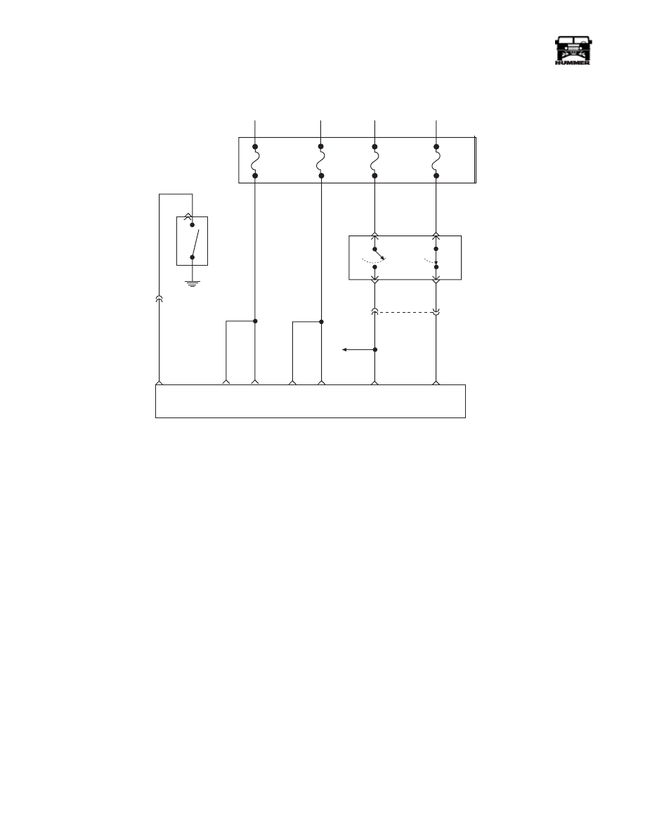
DTC P1875 Four-Wheel Drive Low Switch
Fault
Circuit Description
The 4WD low circuit consists of a 4WD indicator, switch, and
wiring. When the operator moves the shift lever to 4 Low, the
4WD indicator lamp will illuminate and circuit 784 voltage to
the PCM will change from B+ to zero. The 4WD low switch
signal is used to correct transmission output speed signal to
PCM. This signal is used to compensate for transfer case gear
reduction. The PCM uses the transmission output speed signal
to adjust shift points, line pressure, and converter clutch sched-
uling.
This DTC detects a continuous open or short to ground in the
4WD circuit.
Conditions For Setting DTC
• No DTCs P0121, P0122 or P0123.
• No DTC P0502.
• No 1-2 shift solenoid DTC P0753.
• No 2-3 shift solenoid DTC P0758.
• No DTC P1810.
• No PWM solenoid DTC P1860.
• Engine speed is greater than 400 rpm for 8 seconds.
• Gear range is D4.
• Throttle angle is between 10% and 100%.
• Transmission fluid temperature is between 18-125°C
(68°-248°F).
• Shift solenoid performance counters are zero.
All of the above conditions have been met and either one of the
following fail conditions are true.
• Four wheel drive low is stuck “on” for 2 seconds. Gear
ratio between 0.95 and 1.05:1.
• Four wheel drive low is stuck “off” for 3 seconds. Gear
ratio between 2.66 and 2.76:1 in any two gears.
FUSE 2D
20 AMP
INTERIOR
FUSE 3A
20 AMP
EXTERIOR
FUSE 4D
15 AMP
INTERIOR
FUSE 6B
5 AMP
INTERIOR
10 OR
291 PK
A
D
BRAKE
LAMP
TCC/
CRUISE
B
C
31
40
C1-
TO BRAKE
LAMP
C28-C13
C28-D13
C28-C12 C28-C11
C29-B10
C29-B9
TCC / CRUISE
BRAKE SWITCH
BRAKE LIGHT
SWITCH SIGNAL
IGNITION
VOLTAGE
BATTERY
POSITIVE
537 OR
POWERTRAIN
CONTROL
MODULE (PCM)
239 PK
9-S12-069.1
C27-D2
TRANSFER
CASE RANGE
SWITCH
C33-J
Нет комментариевНе стесняйтесь поделиться с нами вашим ценным мнением.
Текст