Hummer H1 (2002+). Manual — part 161
_____________________________________________________________________
Body 10-15
®
05745159
Crashpad Replacement (Right Side)
Removal
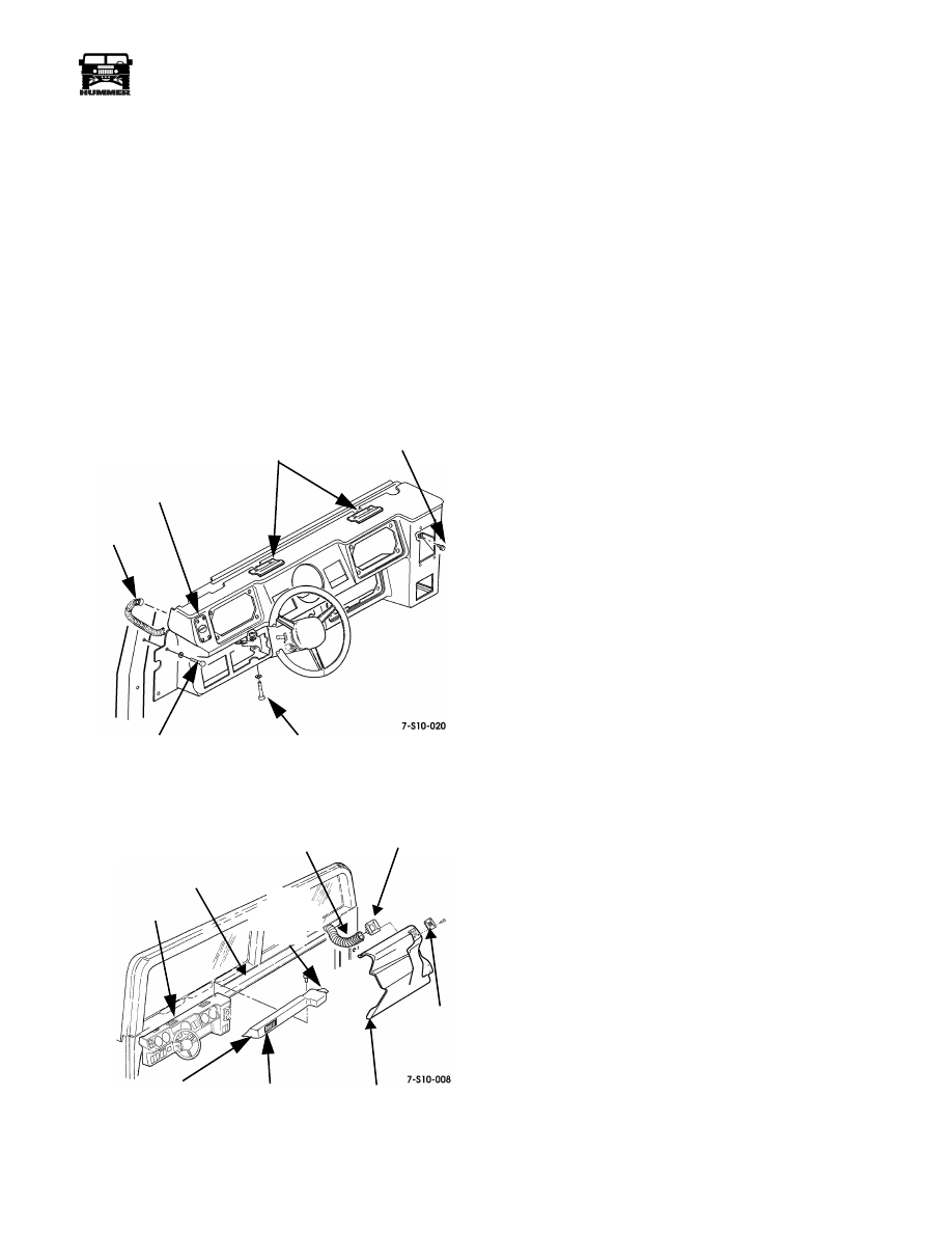
1.
Remove screw/washers, and crashpad from dashboard
(Figure 10-16).
2.
Disconnect air hose from vent duct.
3.
Remove screws, side window vent, and vent duct from
crashpad.
Installation
1.
Secure vent duct and window vent to crashpad with screws
(Figure 10-16).
2.
Connect air hose to vent duct.
3.
Secure crashpad to dashboard with screw/washers.
Figure 10-15: Instrument Panel Replacement
Figure 10-16: Crashpad Replacement
Crashpad Replacement (Left Side)
Removal
1.
Remove screw/washers from top of crashpad.
2.
Tug gently on crashpad toward steering wheel to free
crashpad clips from I. P. clips (Figures 10-15 and 10-16).
3.
Lift vent side of crashpad and work console side (duct
nozzle) out of front console.
Installation
1.
Work console side (duct nozzle) of crashpad into front
console plenum.
2.
Position crashpad on edge of I. P. closest to steering wheel
and push crashpad onto I. P. clips (Figures
10-15
and 10-16).
3.
Secure crashpad to I. P. with screw/washers.
AIR
HOSE
SIDE WINDOW
DEFROST VENT
RIGHT SIDE
MOUNTING BOLT
STEERING COLUMN
MOUNTING BOLTS
LEFT SIDE
MOUNTING BOLTS
I. P. CLIPS
DASHBOARD
AIR HOSE
VENT
DUCT
WINDOW
VENT
CRASH PAD
(RIGHT SIDE)
CRASH PAD
(LEFT SIDE)
VENT
DUCT
CONSOLE
NOZZLE/
SIDE
I. P. CLIPS

10-16
Body
______________________________________________________________________
®
Gauge Replacement
NOTE:
Gauge replacement is basically the same for all instru-
ment panel gauges.
Removal
1.
Remove screws and pull gauge panel away from instru-
ment panel (Figure 10-17).
2.
Disconnect lamp connector from gauge.
NOTE:
Tag all leads prior to removal for installation.
3.
Remove nut and lockwasher assemblies securing three
leads to gauge.
4.
Remove hold-down bracket.
5.
Remove gauge through front of gauge panel.
Figure 10-17: Gauge Replacement
Installation
1.
Insert gauge through front of gauge panel (Figure 10-17).
2.
Secure hold-down bracket and lead to gauge with nut and
lockwasher assembly.
3.
Secure leads to gauge with nut and lockwasher assemblies.
4.
Connect lamp connector to back of gauge.
5.
Start engine and ensure gauge operates properly.
6.
Secure gauge panel to instrument panel with screws.
Instrument Panel Indicator Lamp
Replacement
NOTE:
All instrument panel indicator lamps are replaced basi-
cally the same.
Removal
1.
Remove instrument panel.
2.
Turn lamp socket one-quarter turn counterclockwise, and
remove socket from indicator light housing.
3.
Pull lamp from socket (Figure 10-18).
Installation
1.
Push lamp into socket (Figure 10-18).
2.
Insert socket into status center and secure by turning
socket clockwise one-quarter turn.
3.
Install instrument panel.
4.
Start engine and ensure lamp operates properly.
Figure 10-18: Instrument Panel Indicator Light
Replacement
LAMP
INSTRUMENT
LEADS
HOLD-DOWN
LEAD
GAUGE
GAUGE PANEL
PANEL
CONNECTOR
BRACKET
9-S06-015.1
BULB SOCKET
STATUS CENTER
_____________________________________________________________________
Body 10-17
®
05745159
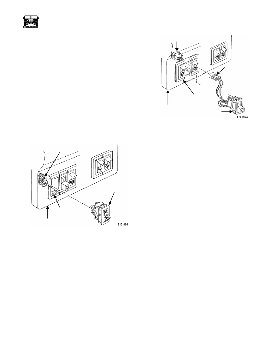
Instrument Panel Switch Replacement
NOTE:
All instrument panel switches are replaced similarly,
with the exception of the dimmer control switch. This proce-
dure covers the main light switch.
CAUTION:
Some connectors can be installed incorrectly and
cause damage to the electrical system. Make note of connector
position prior to removal.
Removal
1.
Remove closeout panel.
2.
Reach up behind IP and push switch from switch housing.
3.
Remove connector from switch (Figure 10-19).
Installation
1.
Install connector on switch (Figure 10-19).
2.
Install switch in switch housing.
3.
Install closeout panel.
Figure 10-19: Instrument Panel Switch Replacement
Instrument Panel Dimmer Control Switch
Replacement
Removal
1.
Remove closeout panel.
2.
Reach up behind instrument panel and push switch from
switch housing.
3.
Unplug connector from wiring harness (Figure 10-20).
Figure 10-20: Instrument Panel Dimmer Control
Switch Replacement
Installation
1.
Plug connector into wiring harness.
2.
Install switch in switch housing (Figure 10-20).
3.
Install closeout panel.
SWITCH
HOUSING
INSTRUMENT PANEL
CONNECTOR
WIRING HARNESS
CONNECTOR
SWITCH
INSTRUMENT PANEL
HOUSING

10-18
Body
______________________________________________________________________
®
Speedometer/Odometer Replacement
Removal
1.
Remove the left A-pillar dash trim (closeout).
2.
Remove the left footwell closeout panel and disconnect
the courtesy light plug, diagnostic link connector and the
footwell vent hose from the closeout panel.
3.
If equipped with power mirrors, pop the switch from dash
and let hang to gain access to the crossbolt nut.
4.
Remove the two screws securing the harness hanger to the
steering column mount bracket and remove the harness
hanger.
5.
Loosen the two bolts at the forward steering column pivot
point.
6.
Remove the steering column crossbolt, nut and washer and
tilt the steering column downward.
7.
Remove the left and right gauge bezels (with gauges), for
access to the rear of the speedometer/odometer, and let the
bezels lay loose.
8.
Remove two trim screws from the crashpad and pull
rearward to release the crashpad.
9.
Remove the two plastic protector caps from the rear of the
speedometer/odometer mounting studs.
10. Remove the wire connector from the backside of the
speedometer.
11. Remove the two speedometer/odometer hold-down
bracket nuts and lockwashers and the hold-down bracket.
12. Pull the speedometer/odometer from the dash and remove
the two remaining nuts and lockwashers that secure the
ground and sending lead connections.
Installation
1.
Insert speedometer/odometer into instrument panel and
secure with hold-down bracket, electrical connector, and
nut and lockwasher assemblies (Figure 10-21).
2.
Slide two plastic protector caps onto the speedometer/
odometer mount studs.
3.
Install the crashpad using two trim screws.
4.
Install the left and right gauge bezels.
5.
Tilt the steering column up and install the crossbolt, nut
and washer.
6.
Tighten the two bolts at the forward pivot point of the
steering column.
7.
Screw the harness hanger to the steering column mount
bracket.
8.
Install the power mirror switch if removed in step 3 above.
9.
Install the footwell vent hose, the DLC, the courtesy light
plug and the left footwell closeout panel.
10. Install the left A-pillar dash trim (closeout).
Figure 10-21: Speedometer/Odometer Replacement
HOLD-DOWN
PIVOT BOLT
POWER
CROSSBOLT
HARNESS
SPEEDOMETER/
HANGER
BRACKET
ODOMETER
MIRROR
SWITCH
POWER
MIRROR
SWITCH
4-1-00
Нет комментариевНе стесняйтесь поделиться с нами вашим ценным мнением.
Текст