Hummer H1 (2002+). Manual — part 162

_____________________________________________________________________
Body 10-19
®
05745159
Tachometer Replacement
NOTE:
Mark position of set screws in relationship to tachom-
eter clock panel before disassembly. Tachometer mounting
clamp must be installed in factory position to have proper
clearance for reassembly.
NOTE:
It may be necessary to remove clock for access to ta-
chometer mounting clamp hardware.
Removal
1.
Remove screws and tachometer/clock panel from I.P.
2.
Unplug tachometer electrical connector from I.P. wiring
harness.
3.
Loosen set screws and tachometer mounting clamp
hardware. Remove clamp from tachometer housing.
4.
Remove tachometer from tachometer/clock panel.
Installation
1.
Position tachometer in tachometer/clock panel.
2.
Slide tachometer mounting clamp onto tachometer
housing; close enough to tachometer/clock panel for set
screws to make contact.
3.
Tighten clamp securely onto tachometer body and tighten
setscrews until they contact tachometer/clock panel.
4.
Plug tachometer electrical connector into I.P. wiring
harness.
5.
Secure tachometer/clock panel to I.P. with screws.
Figure 10-22: Tachometer Mounting
CIGARETTE LIGHTER REPLACEMENT
Removal
1.
Pull front console away from dashpad enough to gain
access to wiring harness connector.
2.
Remove wiring harness connector from lighter assembly.
3.
Remove element from lighter assembly heater (Figure 10-23).
4.
Remove shell from heater, and remove shell, heater, and
bezel from console.
Installation
1.
Install bezel and heater in console (Figure 10-23).
2.
Install shell on heater.
3.
Install wiring harness connector on lighter assembly.
4.
Install element in lighter assembly.
5.
Engage cigarette lighter to ensure proper operation.
6.
Install front console.
Figure 10-23: Cigarette Lighter Breakdown
GLOVEBOX REPLACEMENT
Removal
Remove screws and glovebox from front console (Figure 10-24).
Installation
Secure glovebox to front console with screws (Figure 10-24).
Figure 10-24: Glovebox
PASSED
PASSED
P
A
S
S
E
D
6-S10-018.1
TACHOMETER
MOUNTING
CLAMP
TACHOMETER
MOUNTING
CLAMP
HARDWARE
SET SCREW
CLOCK MOUNTING
CLAMP
CLOCK
TACHOMETER
TACHOMETER/CLOCK
PANEL
WIRING HARNESS
SHELL
ELEMENT
HEATER
CONSOLE
CONNECTOR
LIGHTER
ASSEMBLY
BEZEL
GLOVEBOX
FRONT CONSOLE

10-20
Body
______________________________________________________________________
®
ASHTRAY REPLACEMENT
Removal
1.
Pull front console away from dashpad to gain access to
ashtray frame tabs.
2.
Pull ashtray receptacle out of frame (Figure 10-25).
3.
Straighten frame tabs and remove frame.
Installation
1.
Insert frame into opening on console and secure it by
bending tabs around opening.
2.
Push ashtray receptacle into frame (Figure 10-25).
3.
Install front console.
Figure 10-25: Ashtray Mounting
ENGINE ACCESS COVER
Inner Engine Access Cover Flexible Latch
and Hold-Down Striker Replacement
Removal
1.
Remove engine access cover.
2.
Remove rivets and hold-down striker from body
(Figure 10-26).
3.
Remove rivets and flexible latch from cargo floor.
Installation
1.
Secure flexible latch to cargo floor with rivets (Figure 10-26).
2.
Secure hold-down striker to body with rivets.
3.
Install engine access cover.
Figure 10-26: Inner Engine Access Cover Latch
Location
Engine Access Cover Replacement
Removal
1.
Remove console.
2.
Unlatch flexible latches from keepers on engine access
cover hold-down brackets (Figure 10-27).
3.
Unlatch engine access cover hold-down latches from
engine access cover hold-down strikers.
4.
Turn ring studs and remove access cover.
Figure 10-27: Engine Access Cover Replacement
6-S10-122
ASHTRAY
ASH TRAY
RECEPTACLE
TABS
(AFTER BENDING)
FRAME
FRONT
CONSOLE
TABS
(BEFORE
BENDING)
FLEXIBLE
BODY
CARGO FLOOR
LATCH
HOLD-DOWN
STRIKER
ENGINE
FLEXIBLE
RING STUDS
HOLD-DOWN STRIKER
HOLD-DOWN BRACKET
LATCH
ACCESS
COVER
HOLD-DOWN LATCH
AND KEEPER
_____________________________________________________________________
Body 10-21
®
05745159
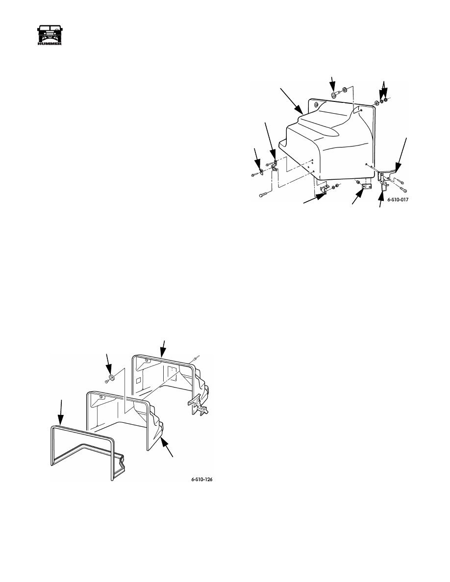
Disassembly
1.
Remove rivets, retainers, and insulation from engine
access cover (Figure 10-28).
2.
Remove seal from access cover.
3.
Remove retaining rings, washers, and ring studs from
access cover (Figure 10-29).
4.
Remove locknuts and shoulder bolts securing latch guide
plates and back plates to access cover and remove latches.
5.
Remove rivets, latch guide plates, and back plates from
access cover.
6.
Remove rivets and keepers from hold-down brackets.
7.
Remove rivets, nuts, washers, screws, hold-down
brackets, and backing plates from access cover.
Assembly
1.
Secure hold-down brackets and backing plates to access
cover with rivets, screws, washers, and nuts (Figure 10-29).
2.
Secure keepers to hold-down brackets with rivets.
3.
Secure latch guide plates and back plates to access cover
with rivets.
4.
Secure latch guide plates to back plates and access cover
with shoulder bolts and locknuts. Install latches.
5.
Secure washers and ring studs to access cover with
washers and retaining rings.
6.
Install seal on access cover (Figure 10-28).
7.
Secure insulation to access cover with rivets and retainers.
Figure 10-28: Engine Access Cover, Insulation, and
Seal Breakdown
Figure 10-29: Engine Access Cover Fastener
Positioning
Installation
1.
Position engine access cover and fasten ring studs
(Figure 10-29).
2.
Secure hold-down latches on hold-down strikers.
3.
Latch flexible latches on hold-down bracket keepers.
4.
Install console.
SEAL
RETAINER
ENGINE ACCESS
COVER
INSULATION
RING STUD
RETAINING
LATCH
HOLD-DOWN LATCH
BACK PLATE
BACKING
KEEPER
HOLD-DOWN
ENGINE
BRACKET
RINGS
GUIDE
PLATE
PLATE
ACCESS COVER
10-22
Body
______________________________________________________________________
®
SEAT BELT ASSEMBLY REPLACEMENT
NOTE:
Replacement of the seat belt assembly is basically the
same for all seat locations on all vehicle models. This proce-
dure covers the left front seat belt on four-door hard top vehi-
cles.
Removal
1.
Remove seat.
2.
Remove screw/washer assembly, seat buckle, and washer
from body (Figure 10-30).
3.
Remove inner kick panel enough to gain access to seat
buckle electrical connector.
4.
Disconnect seat buckle electrical connector from roof
harness connector and pull seat buckle electrical connector
through grommet in inner kick panel.
Figure 10-30: Seat Belt Electrical Connector
Location
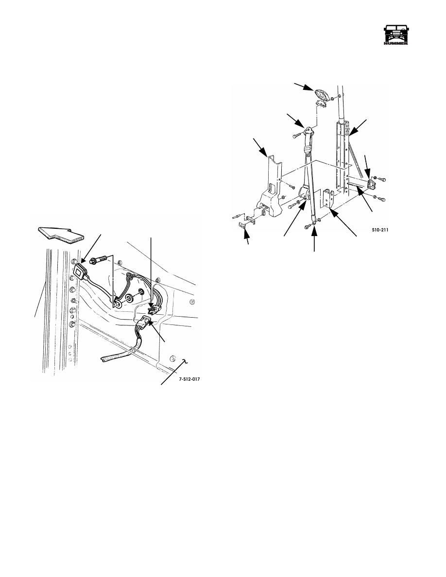
5.
Remove screw/washer assembly, D-ring, webbing guide
cover, and washer from B-pillar (Figure 10-31).
Figure 10-31: Seat Belt Assembly Breakdown
6.
Remove screw/washer assembly, anchor bracket, and
washer from bracket.
NOTE:
Steps 8 and 9 are applicable to all vehicles except two-
door vehicles with the enlarged cab.
7.
Remove courtesy light lamp assembly, rivets, mounting
bracket, and washers from lower B-pillar trim (Figure 10-31).
8.
Disconnect body harness connector from courtesy light
lamp assembly.
9.
Remove screw/washer assemblies securing lower B-pillar
trim to B-pillar.
10. Remove bolt, washer, and retractor from retractor
mounting bracket. Remove seatbelt assembly from lower
B-pillar trim.
11. Remove bolts, washers, and retractor mounting bracket
from B-pillar.
12. Remove bolts, washers, and bracket from B-pillar and
body.
SEAT
SEAT BELT
INNER
ROOF
KICK PANEL
ELECTRICAL
CONNECTOR
HARNESS
CONNECTOR
BUCKLE
WEBBING
GUIDE
COVER
RETRACTOR
D-RING
ANCHOR
BRACKET
BRACKET
BODY
RETRACTOR
BRACKET
B-PILLAR
MOUNTING
LOWER
B-PILLAR TRIM
COURTESY
LIGHT
Нет комментариевНе стесняйтесь поделиться с нами вашим ценным мнением.
Текст