Hummer H1 (2002+). Manual — part 26

____________________________________________________________________
Engine 2-65
®
05745159
Figure 2-110: Removing Cam Bearings 1 and 5
CAUTION: It is extremely important that the cam bearings be
properly aligned during installation. Failure to align the oil
feed holes in the bearings and oil feed slots in the bearing
bores, will result in engine failure.
6.
Note ID numbers on new bearings. Place bearings in order
to maintain correct installation sequence.
7.
Mark center position of oil slot in each bearing bore with
grease pencil or chalk. Place marks adjacent to each
bearing bore so it is easily viewed. Make two marks for
no. 1 bearing to ensure that both oil holes will be aligned.
8.
Align oil hole in new No. 5 bearing with J–6098-01
alignment mark on block. Seat bearing in block with
driver handle and adapter J–6098-12 (Figure 2-111).
9.
Align both oil holes in new No. 1 bearing with oil holes in
block (Figure 2-111). Bearing notch should be facing out
and seam at 11 O’clock position. Seat bearing in block
with driver handle and adapter J–33049 (Figure 2-111).
10. Check installation of bearing number 1 and 5. Verify that
bearing oil holes are centered on slots in bores and that
bearings are flush with edges of bearing bores. The small
groove in each bearing should be towards upper part of
block. Remove and reposition either bearing if misaligned
(Figure 2-111).
11. Install remaining bearings, starting with No. 2, as follows:
a.
Insert pilot in No. 1 bearing.
b.
Slide puller screw through pilot and No. 2 bearing
bore (Figure 2-112).
c.
Position new bearing on adapter J–33049
(Figure 2-112).
d.
Secure adapter to puller screw.
e.
Align bearing oil hole with paint mark on block.
f.
Tighten puller screw to draw bearing into place.
g.
Verify that bearing oil hole is properly aligned.
h.
Install bearings 3 and 4 in same manner.
Figure 2-111: Installing Cam Bearings 1 and 5
Figure 2-112: Installing Cam Bearings 2,3, and 4
ADAPTER
NO. 5
NO. 1
DRIVER
HANDLE
ADAPTER FROM
J–6098-01
DRIVER
HANDLE
J–6098-01
SET J–33049
J–6098-12
NO. 1BEARING
J–6098-01
OIL HOLE (1)
NO. 5 BEARING
ADAPTER J–6098-12
J–6098-01
ADAPTER
DRIVER HANDLE
FROM
J–33049
DRIVER
HANDLE
BEARING
SEAM AT
11 O’CLOCK
OIL HOLE
AT 4:30
POSITION
OIL HOLE
AT 1 O’CLOCK
POSITION
PLUG
ADAPTER J–6098-11
NO. 2 BEARING
BEARING BORE
PILOT FROM
PULLER SCREW
CAMSHAFT
FROM J–33049
J–33049
2-66
Engine
_____________________________________________________________________
®
CRANKSHAFT SERVICE
Clean the crankshaft with solvent and clear the journal oil
holes with a wire brush if necessary. Dry the crankshaft with
compressed air or lint free shop towels.
Inspect condition of rod and main journals (Figure 2-113). The
journals must be smooth and free from scoring, grooves, taper,
cracks, and checking/galling.
Minor nicks and burrs can be removed with an oil stone and
380 grit emery. Minor scratches, or scoring on journal surfaces
can be smoothed with 320 grit emery followed by polishing
with crocus cloth.
Check for cracks on all surfaces including the counterweights.
Also check the threads in the crankshaft flange and nose.
Rusty, rough threads can be cleaned up with a tap. However,
replace the shaft if the threads are seriously damaged.
Magnaflux or Zyglo the crankshaft if cracks are suspected.
Although the crankshaft journals can be machine polished to
restore surface finish, replace the crankshaft if damaged, dis-
torted, worn, or scored. Do not attempt to salvage it.
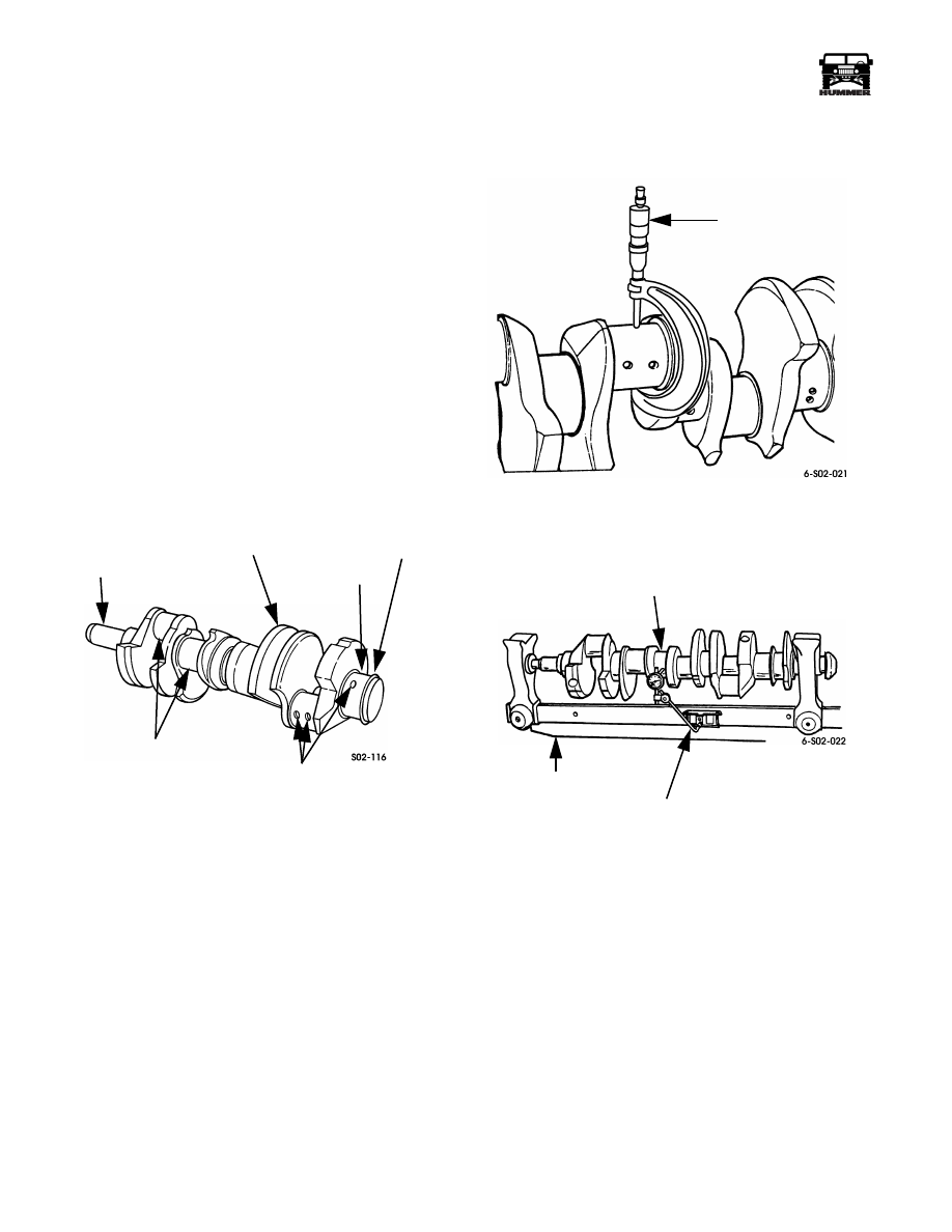
Figure 2-113: Crankshaft Inspection Points
Checking Crankshaft Journal Diameter and
Runout
There are three main journal diameter ranges. These ranges are
identified by a color code paint mark near one of the journals.
The three size range color codes are blue, orange/red, and
white. Note the code on the crankshaft and refer to the specifi-
cation charts at the end of this section for size ranges.
Use a micrometer to check journal diameter. Measure both
ends of each journal to check for taper along with wear
(Figure 2-114).
Journal wear or taper must not exceed 0.0002-0.001 in. (0.05-
0.025 mm).
Mount the crankshaft in a holding fixture and check runout at
center (#3) main bearing journal (Figure 2-115).
Crankshaft runout should not exceed 0.0002 - 0.0008 in. (0.005
- 0.020 mm). Replace the crankshaft if runout is greater than
specified. Do not attempt to straighten a cast iron crankshaft.
Figure 2-114: Measuring Journal Diameter
Figure 2-115: Measuring Crankshaft Runout
ROD JOURNAL
COUNTERWEIGHT
MAIN JOURNAL
SEAL SURFACE
OIL HOLES
NOSE
MICROMETER
CENTER
MAIN JOURNAL
DIAL INDICATOR
HOLDING FIXTURE
J–8001

____________________________________________________________________
Engine 2-67
®
05745159
PISTON/CONNECTING ROD OVERHAUL
Remove and discard the old piston rings. Use a remover/in-
staller tool similar to parallel jaw type tool shown
(Figure 2-116). Discard rings after removal.
Use a ring groove tool to remove carbon and oil deposits from
the ring grooves. Using a section from an old piston ring is not
recommended for this purpose.
Disassembly the piston, and rod as follows:
a.
Note piston-to-rod position for assembly reference.
b.
Remove retaining rings that secure piston pin. Discard
rings; they are not reusable.
c.
Push piston pin out of piston and rod.
d.
Separate piston, and rod, and pin (Figure 2-117).
Clean the piston, rod, and pin with solvent and carb cleaner if
needed. Do not use a wire brush or any type of abrasive on the
piston.
Inspect piston condition. Replace the piston if cracked, se-
verely scuffed or scored, the ring lands are worn or damaged,
or the skirt is collapsed (Figure 2-118).
Measure pin bore diameter in the piston (Figure 2-119). Then
measure diameter of the piston pin (Figure 2-119). The differ-
ence between pin diameter and bore diameter, should be
0.0004 - 0.0006 in. (0.010-0.0153 mm). This figure represents
the required pin-to-bore clearance. Replace the piston and pin
as a set if clearance is greater than specified.
NOTE:
Turbo diesel and NA diesel piston and rod assemblies
are different. Do not interchange them.
Figure 2-116: Piston Ring Removal/Installation Tool
Figure 2-117: Connecting Rod and Piston Assembly
Figure 2-118: Piston Inspection Points
PISTON RING
REMOVER/INSTALLER
TOOL
TOP COMPRESSION RING
BOTTOM
OIL RING
RETAINING RING
PISTON
PISTON PIN
RETAINING RING
PIN BUSHING
CONNECTING ROD
ROD CAP
COMPRESSION
RING
ROD
BOLT
ASSEMBLY
CROWN
GROOVE
LAND
PIN BORE
SKIRT
Section 2 Engine

2-68
Engine
_____________________________________________________________________
®
Figure 2-119: Measuring Piston Pin Diameter
Measure pin bushing diameter in connecting rod with small
bore gauge or inside micrometer (Figure 2-120). Record bush-
ing diameter and compare it to diameter of new or known good
piston pin. The difference between the two measurements rep-
resents the piston pin-to-connecting rod pin bushing clearance.
Required clearance is 0.0003-0.001 in. (0.0081-0.0309 mm).
Replace the connecting rod if the bushing is worn oversize.
The bushing is not serviced separately.
Figure 2-120: Checking Connecting Rod Pin
Bushing Diameter
Check connecting rod straightness in a rod fixture, or on a sur-
face plate or sheet of glass. The rod can be straightened if dis-
tortion is less than 0.002 in. (0.05 mm) end-to-end. Replace the
rod if severely bent, twisted, or cracked.
Measure piston skirt diameter at, or just below the pin bore
centerline. The correct gauge point is approximately 2.57 in.
(65.3 mm) down from the piston crown (Figure 2-121). Be
sure measurement is taken at a point opposite (at right angle to)
the pin bore centerline as shown. Replace the pistons if wear is
such that piston-to-bore clearance would be greater than:
• 0.004 in. (0.120 mm) for cylinder 1-6 and
• 0.005 in. (0.133 mm) for cylinder 7 and 8
Figure 2-121: Measuring Piston Skirt Diameter at
Gauge Point
Piston Selection and Fit
Production engines are equipped with different grade size pis-
tons. The different grades allow factory select fitting of pis-
tons. Correctly, three grades are used with the ID letters JT,
KT, and GT or J, K, G, or T. The different grades are to accom-
modate minor variances in bore size. The ID letters are on the
cylinder block pan rails adjacent to each cylinder bore, or the
piston itself. The grade sizes are described in the piston and
bore size chart at the end of this section.
Some general selection recommendations are:
• If an original piston is in good condition and meets all
specifications, it can be reused.
• If the cylinder bore is OK but the piston was damaged,
just use a new piston of the same grade size.
• If the piston grade size is not marked on the piston or
pan rail, and the original piston is not reusable, select a
piston that will provide the required piston-to-wall
clearance. It is only necessary to know the actual bore
size.
• The largest oversize piston available is 0.020 in. (0.50 mm).
• It is not necessary to rebore all the cylinders on a low
mileage engine. Only the damaged cylinder needs to be
repaired. This is permissible because factory service re-
placement and original pistons are all the same weight.
Balance is not affected. However, it is recommended
that all the pistons be replaced and the cyliners be re-
bored on high mileage engines.
MICROMETER
PISTON PIN
BORE GAUGE
(OR INSIDE
MICROMETER)
CONNECTING ROD
PIN BUSHING
2.57 in. (65.3 mm)
PISTON SKIRT
MICROMETER
Нет комментариевНе стесняйтесь поделиться с нами вашим ценным мнением.
Текст