Hummer H1 (2002+). Manual — part 195
________________________________________________________
Electrical System 12-7
®
05745159
CIRCUIT MAINTENANCE AND REPAIR
All electrical connections must be kept clean and tight. Loose
or corroded connections may cause a discharged battery, weak
starting, dim lights, or possible electrical system damage.
Wires must be replaced or repaired if insulation becomes
burned, cracked, or deteriorated. When replacing a wire, it is
important that the same gauge size wire be used. Refer to wir-
ing diagram for proper wire gauge sizes. Never replace a wire
with one of a smaller size or replace a fusible link wire with a
wire of a larger size. It should also be noted that fusible link
wire utilizes a special insulation covering. When replacing a
fusible link wire, the replacement wire should be the type in
accordance with SAE J156. Further, fusible link wire should
never be shortened or spliced. If a repair is necessary, entire
fusible link wire must be replaced with one of the proper gauge
size, length and insulation type.
Any wire repair must maintain the waterproof integrity of the
vehicle. Any splice located below the 30 in. (76 cm.) fording
level or in a high splash area must be waterproof and heavy
duty adhesive wall shrink tubing should be used as a minimum
in these areas.
Each harness or wire must be held securely in position to pre-
vent damage to insulation caused by vibrating and chafing.
NOTE:
Before performing any wire repair, disconnect battery
ground cable.
Ground Point legend
G1 - Engine ground-Intake Manifold
G2 - Ground Buss Exterior Fuse Box
G3 - Body Ground
G4 - Instrument Panel Ground Buss Interior
G5 - Frame Ground
Wiring Repair
Wiring harness and wires - All wires are of a specific insula-
tion color indicated on the wiring diagrams. Insulation color
helps to identify circuits and make correct connections. Insula-
tion colors and their abbreviations are as follows:
BK - Black
PK - Pink
BR - Brown
PP - Purple
DB - Dark Blue
RD - Red
DG - Dark Green
GY - Gray
TN - Tan
LB - Light Blue
WH - White
LG - Light Green
YL - Yellow
OR - Orange
Wire repair is very important for the continued, reliable opera-
tion of the vehicle. This repair must be done as described in the
following procedure:
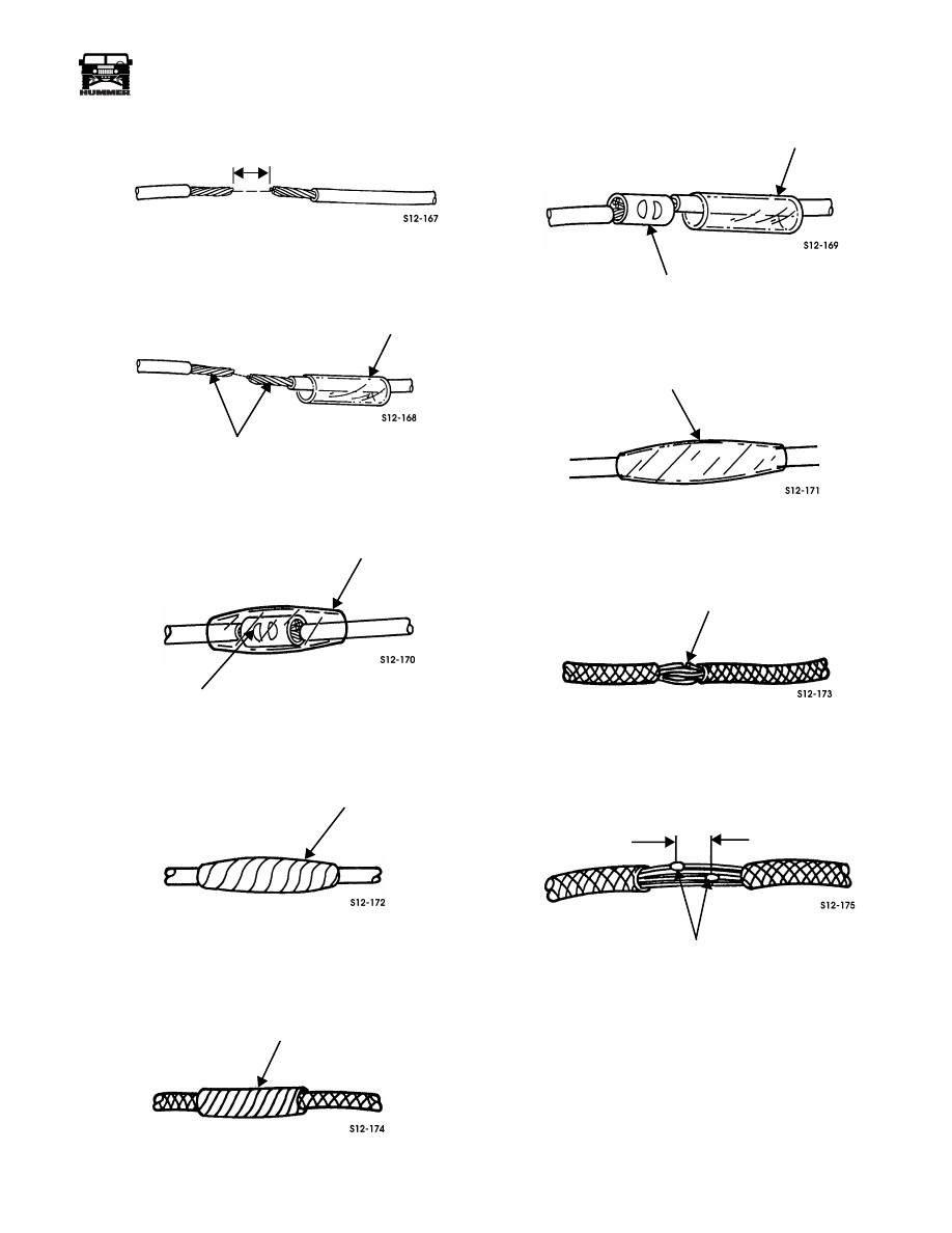
Single Wire Repair (Exposed)
1.
Remove damaged area, removing as little wire as possi-
ble (Figure 12-8).
NOTE:
Care should be exercised in stripping the wire insula-
tion to avoid cutting wire conductor strands.
2.
Strip wire ends to the appropriate length required by the
splice clip (Figure 12-9).
NOTE:
Heat shrink tubing is available in various diameters.
Typically the heat shrink tubing will shrink to approximately
one-half of its original diameter, therefore the tubing diameter
selected for the repair should not be greater than twice the wire
insulation diameter to ensure a proper seal.
3.
Slide heat shrink tubing over one of the wire ends
(Figure 12-10).
NOTE:
Splice clips are available for different wire gauge
sizes. Therefore, it is important to select the appropriate size
for the wire gauge being repaired.
4.
Slide both ends of wire into splice clip and crimp splice
clip to wire ends (Figure 12-11).
5.
Pull wires, by hand, in opposite directions to test the crimp
of the splice clip.
6.
Center heat shrink tubing over splice clip (Figure 12-12).
7.
Using a heat gun or equivalent heat source, apply heat to
heat shrink tubing until tubing conforms to splice clip and
wire insulation (Figure 12-13).
8.
After the splice cools, apply two layers of vinyl adhesive
electrical tape to complete the repair (Figure 12-14).
Single Wire Repair (In a Harness)
1.
Remove harness covering in the affected area
(Figure 12-15).
2.
Repair damaged wire using the exposed single wire repair
procedures. (Go to Step 1.)
3.
After completing the wire repair, apply two layers of vinyl
adhesive electrical tape over the affected area to complete
the repair (Figure 12-16).
Multiple Wire Repair (In a Harness)
NOTE:
Since more than one splice is required in this case,
stagger the wire splices such that they are no closer than 3 in.
(7.6 cm) from each other.
Repair affected wires using the single wire repair (in a harness)
procedures.
4-1-00
12-8
Electrical System
_________________________________________________________
®
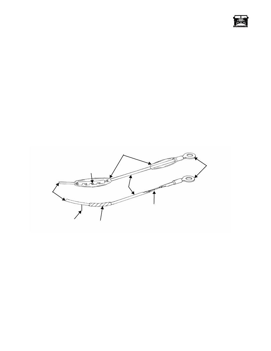
FUSIBLE LINK MAINTENANCE
The following procedure covers the replacement of fusible
links encountered through circuit diagnosis.
1.
Disconnect battery ground cable.
2.
Carefully remove old fusible link from termination
(alternator, power stud, starter).
3.
Locate original wiring harness splice between fusible link
and wiring harness (Figure 12-7).
4.
Cut fusible link splice on harness side. Do not splice into
original fusible link; this may be weakened and cause a
premature failure and repeat problem.
5.
Identify the original fuse link size and length of fuse link
cut from vehicle.
6.
Matching the wire size, cut a length of fusible link wire to
the total length cut from vehicle in Step 4. Be sure to
compensate for any harness wire removed with original
wire. This will avoid overtight wiring that may become
separated with normal operation.
NOTE:
Fusible link is a wire with special insulation. It is im-
portant that replacement material be fusible link wire and it
should be labeled as such. The replacement fusible link should
be between six and nine inches long.
7.
Install a new crimp on connector of the same type and size
as the original lug or connector. Seal connection with low
temperature heat shrink tubing.
8.
Place a piece of heat shrink tubing onto the wire and
install a butt connector onto the fusible link.
9.
Install the fusible link by connecting it to the wiring
harness with the butt connector and heat shrink tubing.
10. Connect terminal end to original location, alternator,
power stud, or starter. Reconnect battery ground cable and
check circuit(s) affected for proper operation.
Figure 12-7: Fusible Link
WIRING
HARNESS
BUTT CONNECTOR
HEAT SHRINK
TUBING
FUSIBLE
LINK
TERMINALS
BURNT SECTION
ORIGINAL
SPLICE
CUT HERE TO
REPLACE LINK
S12-022.3
4-1-00
________________________________________________________
Electrical System 12-9
®
05745159
Figure 12-8: Damaged Wire
Figure 12-9: Heat Shrink Tubing
Figure 12-10: Splice Clip
Figure 12-11: Electrical Tape
Figure 12-12: Electrical Tape
Figure 12-13: Splice Clip
Figure 12-14: Heat Shrink Tubing
Figure 12-15: Damaged Wire
Figure 12-16: Multiple Wire Splice
DAMAGED AREA
STRIPPED WIRE ENDS
HEAT SHRINK TUBING
HEAT SHRINK TUBING
SPLICE CLIP
ELECTRICAL TAPE
ELECTRICAL TAPE
HEAT SHRINK TUBING
SPLICE CLIP
HEAT SHRINK TUBING
DAMAGED WIRE
3.0 INCH
MINIMUM
SPLICE
4-1-00
12-10
Electrical System
_______________________________________________________
®
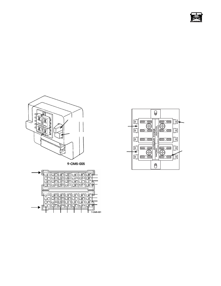
FUSE/RELAY LOCATION AND
IDENTIFICATION
Interior Fuse Box
The interior fuse box, is located under the instrument panel to
the left of the steering column. The fuse box is divided into two
mini-fuse junction blocks, relays, and a auxilliary power
point.The mini-fuse blocks may be accessed without removing
the main fuse box cover (Figure 12-17).
To access relays, the main fuse box cover must be removed.
Before removing any of the fuse box access covers, refer to the
illustrations and charts in this section for the location of specific
fuses, relays, and circuit breakers. Doing this will enable you to
go directly to the fuse or circuit breaker you want to inspect.
Figure 12-17: Interior Fuse Box and Mini Fuse Layout
Fuses and circuit breakers protect the vehicle's electrical sys-
tem from damage caused by overloading. An overloaded cir-
cuit breaker will switch the circuit on again, causing
intermittent operation. A blown fuse will permanently disable
the circuit until the fuse is replaced.
Whenever a fuse blows or a circuit breaker opens a circuit, all
electrical components using that circuit will not operate.
Therefore, during diagnosis of any of these electrical compo-
nents, check the appropriate fuses and circuit breakers for dam-
age (Figure 12-20).
In Line Fuses
Some fuses are placed in-line with the components they are
protecting, meaning they are not located in the fuse box but in
the actual wire suppling current to the device. The only inline
fuse used on the Hummer is in the power feed to the HVAC
high blower relay. This fuse is located on the passenger side of
the engine compartment inside a black plastic cover.
Auxiliary Power Point
An auxiliary power point is provided to ease installation of af-
termarket electrical accessories. The power point is divided
into 2 sections: Ignition and Battery. When a power supply is
needed, a fuse must be installed into one of the empty slots,
and a connection made to the adjacent terminal. The main sup-
ply circuits to both sections of the aux. power point are fused to
30 amps. Total amperage draw on either section should not ex-
ceed 30 amps.
Figure 12-18: Auxiliary Power Point
1
H
G
F
E
D
C
B
A
2
3
4
5
6
7
UPPER
LOWER
BLOCK
MINI-FUSE
MINI-FUSE
BLOCK
INTERIOR FUSE BOX
CTIS BUZZER
FLASHER
9-OM5-006
IGNITION
BATTERY
FUSE SLOT
TERMINAL
4-1-00
Нет комментариевНе стесняйтесь поделиться с нами вашим ценным мнением.
Текст