Hummer H1 (2002+). Manual — part 196
______________________________________________________
Electrical System 12-11
®
05745159
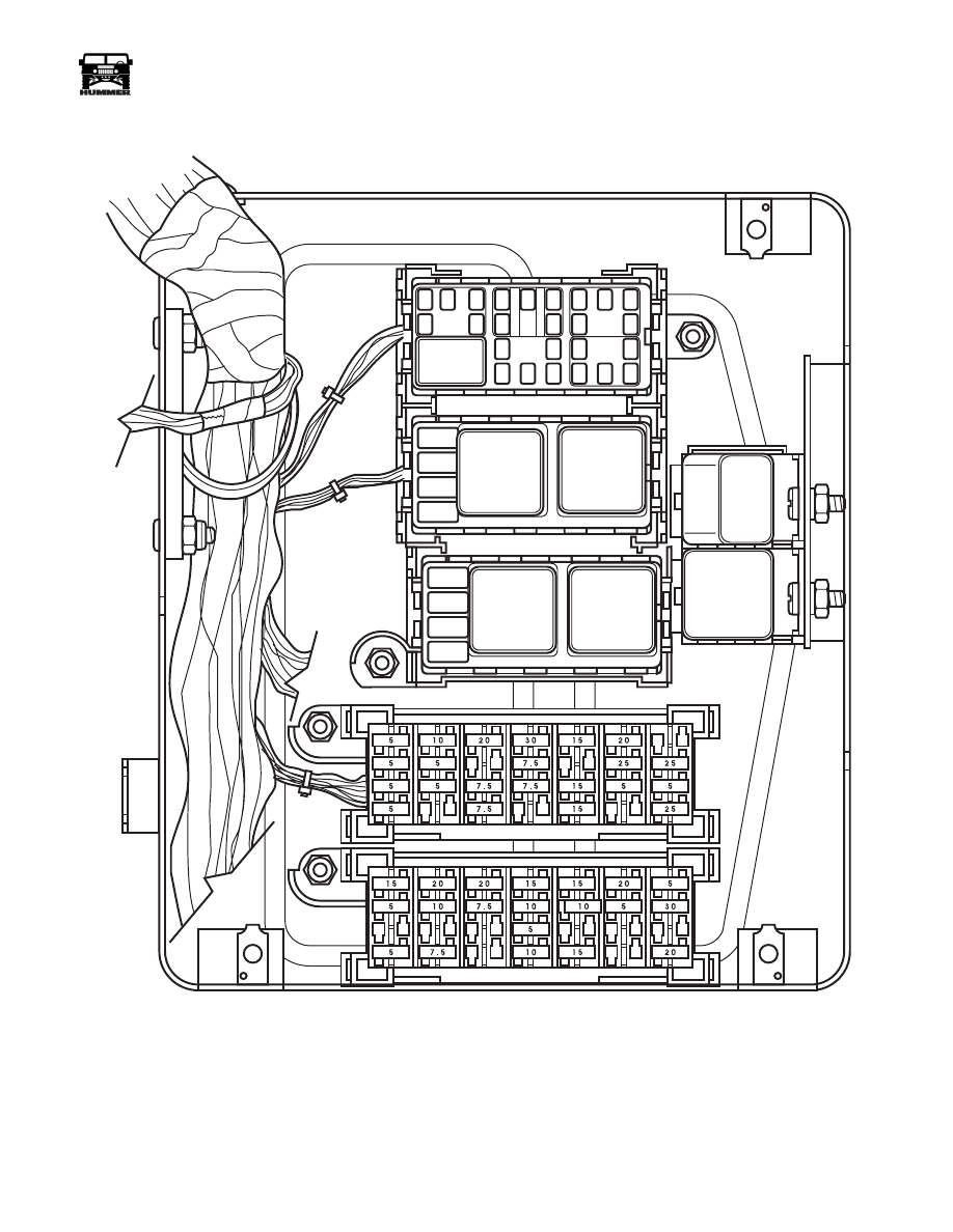
Figure 12-19: Relay Location (Interior Fuse Box)
9-S12-083
C
F
E
B
D
A
B
A
A
B
SIGNAL
FLASHER
CTIS
ALARM
MIRROR
CUTOUT
IGNITION
WIPER
POWER
WINDOW
REAR
WIPER
4-1-00

12-12
Electrical System
_______________________________________________________
®
Upper Mini-Fuse Location
*May not be provided.
Lower Mini-Fuse Location
Figure 12-20: Mini Fuse Identification (Interior Fuse Box)
FUSE
AMPERAGE
CIRCUIT PROTECTED
1E
5
Spare Fuse
2E
–
Blank
3E
7.5
Spare Fuse
4E
–
Blank
5E
15
Spare Fuse
6E
–
Blank
7E
25
Spare Fuse
1F
5
Radio Lights
2F
5
Panel Lights Dimmer Module
3F
7.5
Front Parking/Running Lights
4F
7.5
Rear Parking/Running Lights
5F
15
Trailer Lights
6F
5
Underhood and Trouble Lights
7F
5
Light Circuit to Chime
1G
5
CTIS/Key Chime
2G
5
Power Windows
3G
30
Auxilliary Power Point (Igni-
tion)
4G
7.5
Radio Ignition
5G
–
Blank
6G
25
Rear Wiper/Washer (Slant
Back Only)
7G
25
Windshield Wiper/Washer
1H
5
DLC Power Terminal 16
2H
10
Radio Memory/Clock
3H
20
Power Door Locks/Power
Mirror/ Remote entry Battery
4H
30
Auxilliary Power Point (Bat-
tery)
5H
15
Dome/Courtesy Lights
6H
20
Auxiliary Power Outlet (con-
sole)
7H
25*
Trailer Brake Controller
FUSE
AMPERAGE
CIRCUIT PROTECTED
1A
5
Spare Fuse
2A
7.5
Spare Fuse
3A
–
Blank
4A
10
Spare Fuse
5A
15
Spare Fuse
6A
–
Blank
7A
20
Spare Fuse
1B
–
Blank
2B
–
Blank
3B
–
Blank
4B
5
Gauges/Indicator Lights/MIL
5B
Blank
6B
5
Transmission Brake Switch
7B
5
Remote entry igniton Feed
1C
5
Transmission Shifter Lock/
Heated Windshield
2C
10
A/C Clutch/Rear Defrost/
HVAC Ignition Feed Relay
3C
7.5
Backup Lights
4C
10
Turn Signals
5C
10
Cruise Control
6C
20
HVAC System
7C
30
HVAC Blower
1D
15
Radio Amplifier-Monsoon only
2D
20
PCM Battery/Fuel Lift Pump
3D
20
Cigar Lighters
4D
15
Stoplights
5D
15
Flashers
6D
–
Blank
7D
5
Compass Mirror Battery Feed
4-1-00

______________________________________________________
Electrical System 12-13
®
05745159
Exterior Fuse Box
Figure 12-21: Exterior Fuse Box
The exterior fuse box is located under the hood on the driver’s
side of the engine compartment. The exterior fuse box houses
mini and maxi fuses, circuit breakers, and relays which supply
power to many of the electrical components in the engine com-
partment. The exterior fuse box can be accessed by first
removing the left side cowl cover then removing the fuse box
cover itself. Fuse and relay locations are labled on the inside of
the cover. Spare mini fuses are located in the exterior fuse box
for convient replacement. A fuse puller is also provided to ease
fuse removal.
Figure 12-22: Mini-Fuse Identification
(Exterior Fuse Box)
Figure 12-23: Maxi-Fuse Identification (Exterior Fuse
Box)
Auxiliary Power Studs
The external fuse box provides 2 threaded studs for use as aux-
iliary power connections. Each stud is fused for up to 30 amps
with maxi-fuses located in the external fuse box. Both studs
provide battery power.
Figure 12-24: Auxiliary Power Studs
Ground Points
Two main grounding points are provided to ground vehicle
systems and add-on items. The main grounding stud is located
on the driver’s side of the engine compartment next to the exte-
rior fuse box. The second grounding point is located to the left
of the instrument panel on the interior of the vehicle.
NOTE: Never drill holes in the body to ground electrical
items, the corrosion resistance is compromised, and bad
grounding could result.
FUSE
AMPERAGE
CIRCUIT PROTECTED
1A
–
Blank
2A
10
PCM Ignition Feed
3A
20
Engine Ignition Feed
1B
–
Blank
2B
5
ABS Controller
3B
20
Engine Ignition Feed
1C
25
ABS Valve Relay
2C
30
Heated Windshield
3C
–
Blank
1D
20
Horn
2D
30
Heated Windshield
3D
–
Blank
9-OM5-004
ABS
VALVE
RELAY
HEATED
W/S
HEATED
W/S
RELAY
RELAY
CTIS
PUMP
RELAY
FUEL
PUMP
RELAY.
ABS
WNG.
RLY.
HORN
RELAY
A/C
RELAY
40A
20A CB
30A CB
30A CB
30A CB
30A
40A
40A
40A 30A
30A
#1
#2
#3
#4
#5
#6
#7
#8
#10
#9
25
20
30
30
5
10
20
20
BLANK
BLANK
BLANK
BLANK
5
EXTERIOR
FUSE BOX
FUSE
PULLER
MINI-FUSE LAYOUT
1
2
3
A
B
C
D
MAXI-FUSES
Fuse/
CB
Amperage
Circuit Protected
1
40A
Starter Circuit
2
20A CB
Parking Lights
3
30A CB
Headlights
4
30A CB
Rear Defrost
5
30A CB
Power Windows
6
30A
CTIS Compressor
7
40A
ABS/TT4 Hyd. Pump
8
40A
Ignition Switch Batt Feed
9
30A
Auxiliary power stud A
10
30A
Auxiliary power stud B
9-OM5-004
EXTERNAL FUSE BOX
POWER STUD “A”
POWER STUD “B”
PWR STD A
PWR STD B
MAXI-FUSES
4-1-00

12-14
Electrical System
_______________________________________________________
®
BATTERY CHARGING
General Information
A low charge or discharged battery can be recharged as long as
the cells are not shorted, sulfated, or damaged. Batteries can be
recharged quickly at 20 amp charge levels, or for longer peri-
ods at 10, 5, or 2 amps. A 5 amp charge is preferable.
The battery charger should be equipped with a polarity sensor
to avoid damage through incorrect hookup. Charger capacity
should range from 5 to 20 amps for slow and fast charge rates.
The time and amp rate of charge required will vary depending
on battery condition and temperature. Generally, it takes longer
to recharge a cold battery. State of charge will also affect
charging time as a partially discharged battery may only re-
quire one third the charge time of a fully discharged battery.
There are a number of safety precautions that must be observed
before charging a battery. The following precautions are neces-
sary to avoid personal injury:
Battery Charging Precautions
• Battery electrolyte contains sulfuric acid which can
cause severe burns. Avoid contact with electrolyte by
wearing protective gloves and a face shield. Flush skin
or eyes with water if contact occurs and seek medical
assistance immediately.
• Always wear eye and facial protection when connecting
charging equipment.
• Never attempt to charge a frozen battery. The case could
fracture at the first surge of current.
• Never charge a battery with a low electrolyte level. In-
ternal arcing and battery explosion could occur.
• Never exceed a 20 amp charge with a cold battery. Use a
lower (5-10 amp) rate until the battery warms up.
• Never use excessive charge rates. Reduce charge rate if
the battery becomes overly warm, or if a steady stream
of gas starts to exit the vents.
• Do not use high charge rates on a completely discharged
battery. Use low rates or a trickle charge only.
• Never allow sparks, or an open flame near a charging
battery. The charging process generates hydrogen gas
which is highly inflammable.
• Charge batteries in properly ventilated areas only. Do
not allow hydrogen gas to accumulate and concentrate
in poorly ventilated areas.
Charge Rate and Time
Charge rate will depend on battery temperature and degree of
discharge. Ideally, charging should not proceed until battery
temperature has reached 60°F (16°C). However, in cases where
a cold battery must be charged, start with a 5 amp rate and in-
crease it as battery temperature rises.
In the case of a fully discharged battery, a 24 hour trickle
charge of 1-2 amps is recommended. A 20 amp charge rate
should be used when a battery is only partially discharged.
Suggested charge times are outlined in the charge rate chart
(Figure 12-25). Note that the chart suggested times and rates
are for a battery at 70°F (21°C). Charge times will be greater if
battery temperature is below 55°F (13°C).
Figure 12-25: Charge Rate Chart
Battery Checking Procedures
Visual Inspection
Check for obvious damage, such as a cracked or broken case or
cover or overcharging of the electrical system that could permit
loss of electrolyte. If obvious damage is noted, replace the battery.
Load Test
Before proper testing, the battery must be in a fully charged
state to obtain an accurate test. Load testing requires the use of
battery side terminal adapters to ensure good connections. Do
not attempt to load test a side post battery by screwing bolts
into the terminals as connections.
NOTE: When load testing, batteries must be disconnected
from each other.
1.
Using a battery load tester, measure voltage across the battery
terminals. Normal battery voltage should be 12v or higher.
Recent cranking or load testing will lower the normal voltage.
If no cranking or load testing has been performed, and battery
voltage is below 12v, replace the battery.
2.
Connect battery load tester to the battery to be tested. If
battery has been recently charged, apply a 300 amp load
for 15 seconds to remove the surface charge. Skip this step
if the battery has not been charged.
3.
Wait 15 seconds for the battery to recover. Apply the
necessary load test for the battery being tested. The load
required should be listed on the battery label, if it is not,
use the cold crank amperage divided by 2. (300 cca/2=150
cca)This load should be applied for 30 seconds
4.
If the voltage does not drop below the minimum value, the
battery is good and should be returned to service. The
battery temperature must be estimated by feel and by the
temperature the battery has been exposed to for the
proceeding few hours. If the battery has been exposed to
temperatures below ambient, use the chart below to adjust
the minimum test voltage (Figure 12-26).
4-1-00
Нет комментариевНе стесняйтесь поделиться с нами вашим ценным мнением.
Текст