Hummer H1 (2002+). Manual — part 21
____________________________________________________________________
Engine 2-45
®
05745159
OVERHAUL SERVICE INFORMATION
Anaerobic and RTV type sealers are both used during engine
re-assembly. Anaerobic sealer such as Loctite gasket maker
(515 or 510) is used on the timing chain cover. RTV sealers
such as Permatex Ultra Copper, Ultra Blue, or Loctite 599, are
used on the oil pan and rocker covers.
Thread locking chemicals such as Loctite 242 are specified
wherever necessary. In addition, Permatex dielectric com-
pound can be used on electrical connections to prevent corro-
sion.
Do not use substitute fasteners unless they are of the correct
size and hardness grade. When replacement bolts/nuts are re-
quired, it is recommended that parts catalog items be used.
This ensures that correct grade fasteners are used.
ENGINE REMOVAL
1.
Remove front console attaching screws. Move console
rearward and disconnect console harness connector and
radio harness. Then remove console.
2.
Disconnect Digital Ratio Adapter and Keyless Entry
Module. Remove inner engine cover.
3.
Remove hood with aid of helper as follows:
• Unlatch and lower brushguard, if equipped.
• Unlatch and raise hood.
• Remove clip that attaches hood harness to driver side of
frame.
• Disconnect hood harness from cowl top harness.
• Remove bolts attaching prop and bracket to driver side
air lift bracket. Do not remove prop rod from hood.
Leave rod attached. Tape rod to hood if desired.
• Remove hood hinge pins.
• Remove hood with aid of helper.
4.
Disconnect and remove batteries and cables.
5.
Remove battery tray.
6.
Remove driver and passenger side splash shields.
7.
Drain engine coolant and engine oil.
8.
Discharge A/C system with recovery machine set in
recovery mode.
9.
Disconnect radiator upper and lower hoses at the radiator.
10. Drain fluid in power steering pump using a suction gun.
11. Disconnect oil lines at transmission and power steering
coolers. Cap lines to prevent dirt entry Figure 2-52.
12. Disconnect engine cooler lines for engine oil cooler. Cap
lines to prevent dirt entry.
13. Disconnect A/C lines at condenser. Cap or tape lines and
fittings to prevent dirt entry.
14. Remove rubber/sponge pads from air lift brackets.
15. Remove return hoses from power steering pump.
16. Remove surge tank hose from radiator.
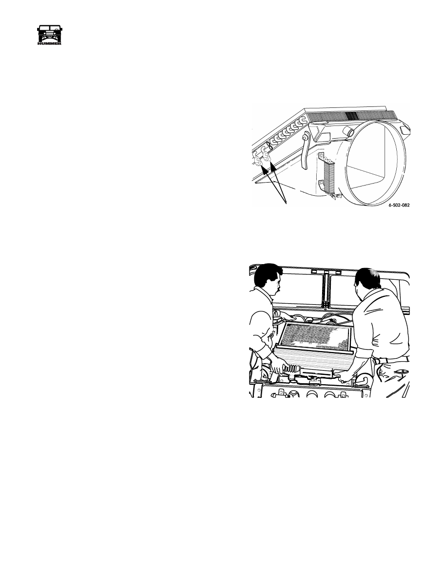
17. Remove bolts attaching radiator and shroud assembly to
frame and brackets. Then (with aid of helper), remove
radiator, shroud, condenser, and oil coolers as an assembly
Figure 2-53.
.
Figure 2-52: Covering Open Ends of Oil
Cooler Lines
Figure 2-53: Radiator, Cooler, Fan Shroud
Removal/Installation
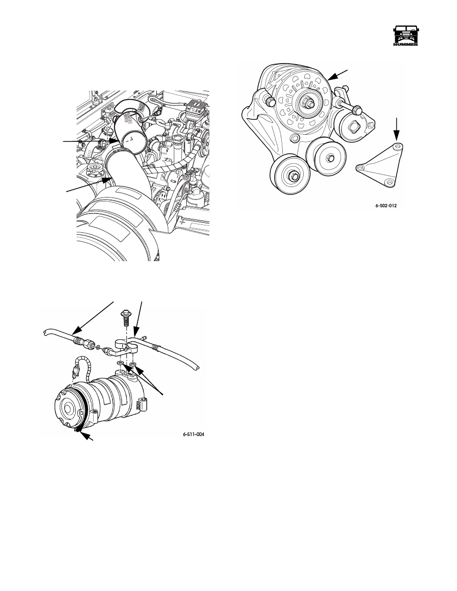
18. Remove air horn from turbocharger and air cleaner hose
(Figure 2-54).
19. Disconnect radiator hose at thermostat housing and at
radiator upper and lower outlets.
20. Remove the engine oil dipstick and tube
21. Loosen tensioner and remove serpentine belt.
22. Using the spanner wrench and ratchet adapter, remove
cooling fan and clutch from water pump.
COVER OPEN ENDS
OF ALL COOLER LINES
WITH DUCT TAPE
6-S02-009
2-46
Engine
_____________________________________________________________________
®
23. Disconnect A/C hoses at compressor. Move hoses aside
for working clearance. Cap open ends to prevent dirt entry
(Figure 2-55).
Figure 2-54: Air Horn and Hose Removal/Installation
Figure 2-55: Suction/Discharge Hose Assembly
Mounting
24. Disconnect bypass hose at water crossover.
25. Disconnect heater hoses at water crossover and water
pump.
26. Disconnect and remove generator, belt tensioner, idler
pulley and bracket as assembly (Figure 2-56).
Figure 2-56: Alternator, Pulleys, and Bracket
Removal/Installation
27. Remove brackets/retainers that secure wire harnesses to
intake manifold and heads.
28. Disconnect AMG wiring harness from starter, glow plug
controller and cowl top harness, then remove.
29. Disconnect wires at all glow plugs.
30. Remove fuel pump from retaining clamp.
31. Disconnect fuel hose from injector pump line at underside
of manifold. Cap all open hose ends.
32. Disconnect injection pump and engine harness connectors.
Move wire harnesses aside for removal clearance.
33. Disconnect glow plug relay wires and cables.
34. Disconnect exhaust pipe at the turbocharger.
35. Remove any remaining brackets and clips securing wire
harnesses to engine.
36. Disconnect oil lines from power steering pump to hydro
boost at hydro boost housing. Cap lines and hydro boost
outlets to prevent dirt entry. Move lines aside for
clearance.
37. Remove turbocharger heat shield and disconnect vacuum
actuator hose.
38. Remove air intake manifold crossover. Tape openings to
prevent dirt entry.
39. Remove intake manifold runners.
9-S03-002
AIR
HORN
AIR
CLEANER
HOSE
SEAL
WASHER (2)
SUCTION/ DISCHARGE
HOSE ASSEMBLY
COMPRESSOR
ALTERNATOR/
IDLER/TENSIONER
AND BRACKET
ASSEMBLY
SUPPORT
BRACKET
____________________________________________________________________
Engine 2-47
®
05745159
40. Working under vehicle, loosen, disconnect, or remove
following:
• Remove skid plate.
• Remove starter and shield (with aid of helper).
• Remove exhaust pipe. Also loosen and move heat shield
aside.
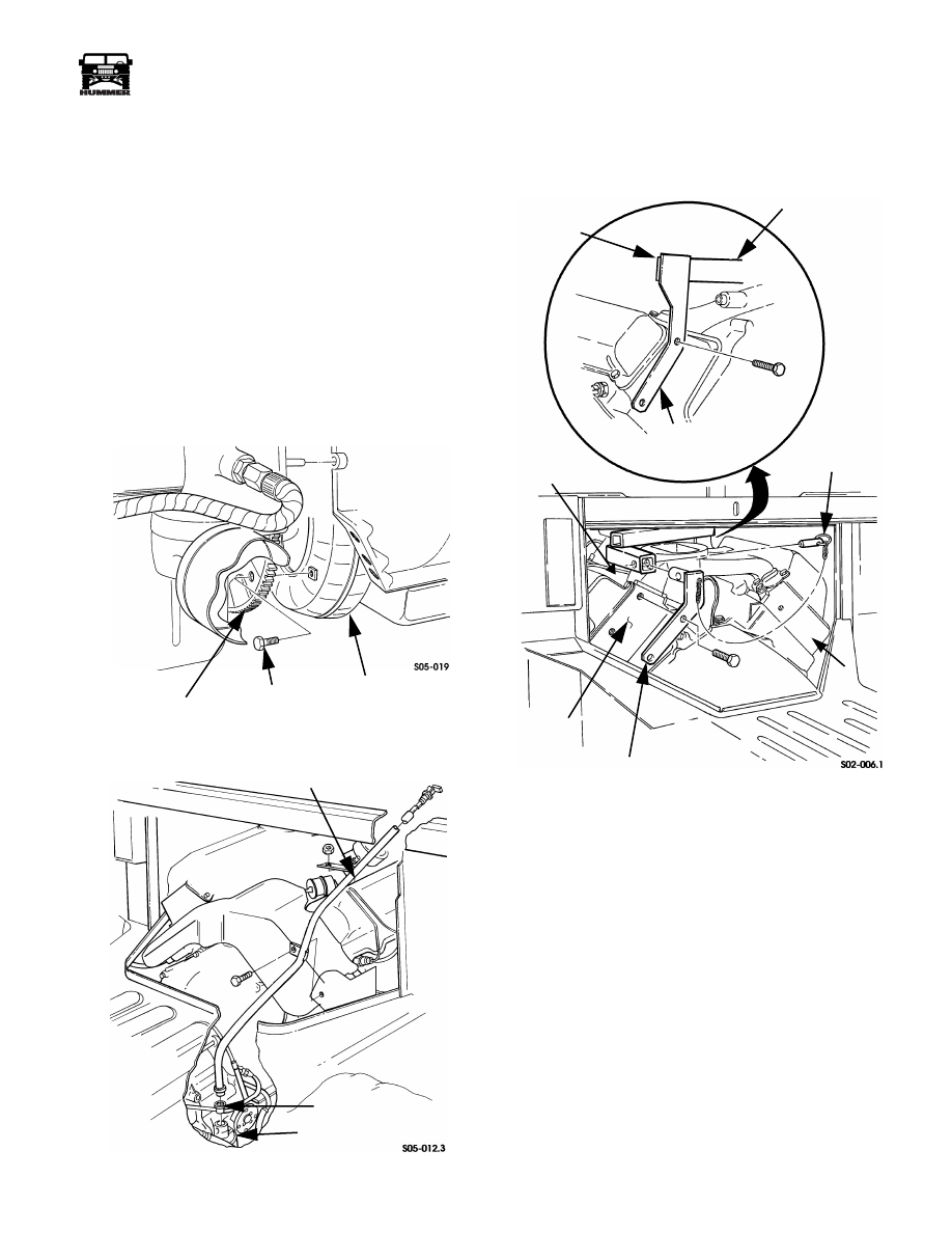
• Remove converter housing access cover and gasket.
• Remove oil filter and disconnect lines to oil cooler.
• Remove transmission fill tube Figure 2-58.
• Remove torque converter attaching bolts Figure 2-57.
• Remove nuts attaching engine mount insulators to frame
brackets.
41. Remove turbocharger.
42. Support transmission with floor jack. Position wood
blocks between transmission and jack saddle.
Figure 2-57: Converter Bolt Removal/Installation
Figure 2-58: Transmission Dipstick Tube
43. Remove bolts/studs attaching transmission to engine
block.
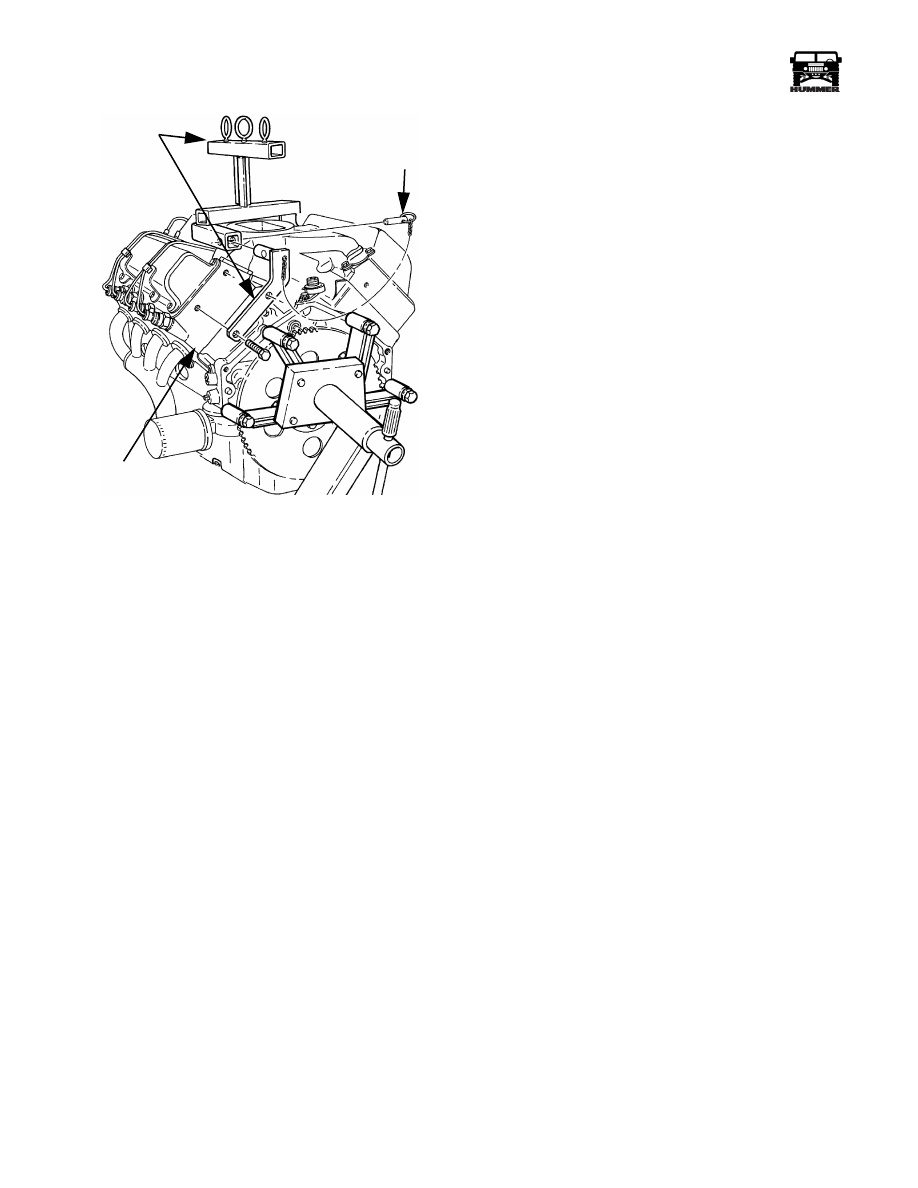
44. Attach lifting sling to engine (Figure 2-59).
Figure 2-59: Lifting Bracket to Cylinder Head
Attachment
45. Raise engine with hoist and remove it from engine bay.
CAUTION:
Make sure all electrical wires, harnesses, and
fluid lines are disconnected and clear of engine assembly. Do
this before removal to avoid damage.
46. Mount engine on heavy duty engine stand or cradle.
Engine stand should have minimum capacity of 1500 lb
(680 kg).
TORQUE
CONVERTER
CONVERTER
BOLT
FLYWHEEL
TRANSMISSION
SEAL
TRANSMISSION FILL/DIPSTICK TUBE
LIFTING BRACKET
FRONT
OF
SLING
RIGHT SIDE
CYLINDER
HEAD (FRONT)
PIN
LIFTING BRACKET
LEFT SIDE
CYLINDER
HEAD
LIFTING
SLING
J–33139
2-48
Engine
_____________________________________________________________________
®
Figure 2-60: Engine Mounted on Repair Stand
ENGINE INSTALLATION
1.
If new engine is being installed, transfer mounting brack-
ets and insulators, generator, power steering pump, A/C
compressor, drive plate (flywheel), turbocharger, and nec-
essary mounting brackets, shields, damper pulleys, sensors
and fittings, from old to new engine.
2.
Attach lifting bracket to engine.
3.
Attach hoist to lifting bracket. Raise engine and guide it
into engine bay with aid of helper.
4.
Align and seat engine on transmission. Be sure converter
pilot hub is seated in crankshaft and that transmission is
seated on engine block dowels. Install 2-3 transmission
attaching bolts (finger tight) to hold engine and
transmission in place.
5.
Align and seat engine mounting bracket insulators on
frame brackets. Be sure insulator studs are fully seated in
frame brackets before proceeding.
6.
Apply Loctite 242 to transmission, converter, and engine
mount nuts/bolts. Then install and tighten nuts and bolts to
following torque:
• Converter bolts to 32 lb-ft (43 N•m)
• Transmission bolts to 35 lb-ft (47 N•m)
• Insulator stud nuts to 90 lb-ft (122 N•m)
7.
Install converter housing access cover. Tighten cover
attaching screws to 60 lb-in. (7 N•m) torque.
8.
Connect engine oil cooler lines to fittings at rear of engine
block.
9.
Install turbocharger.
10. Install starter motor and shield with aid of helper. Tighten
starter mounting bolts to 30-40 lb-ft (41-54 N•m) torque. Do
not connect cable and solenoid wire to starter at this time.
11. Install exhaust pipe and heat shield, if removed and
connect exhaust pipe to turbocharger. Tighten attaching
nuts to 37 lb-ft (50 N•m) torque.
12. Install new oil filter.
13. Install intake manifolds and crossover.
14. Install/connect following:
• Wire harness brackets and clamps
• Injection pump, engine harness, sensor wires
• Turbocharger actuator vacuum hose
• Torbocharger heat shield
• Transmission and engine dipstick tubes
• AMG engine harness
15. Install fuel pump in clamp at driver side of engine bay.
16. Connect fuel lines to injection pump.
17. Install CDR valve and hose if removed.
18. Route hydraulic lines from power steering pump to hydro-
boost unit and connect lines. Be sure lines are clear of hot
or rotating components and are not kinked at any spot.
PIN
LIFTING SLING
AND BRACKET
LEFT
CYLINDER HEAD
J–33139
7-S02-015
Нет комментариевНе стесняйтесь поделиться с нами вашим ценным мнением.
Текст