Hummer H1 (2002+). Manual — part 253
______________________________________________________________
Accessories 13-5
®
05745159
Inspection
1.
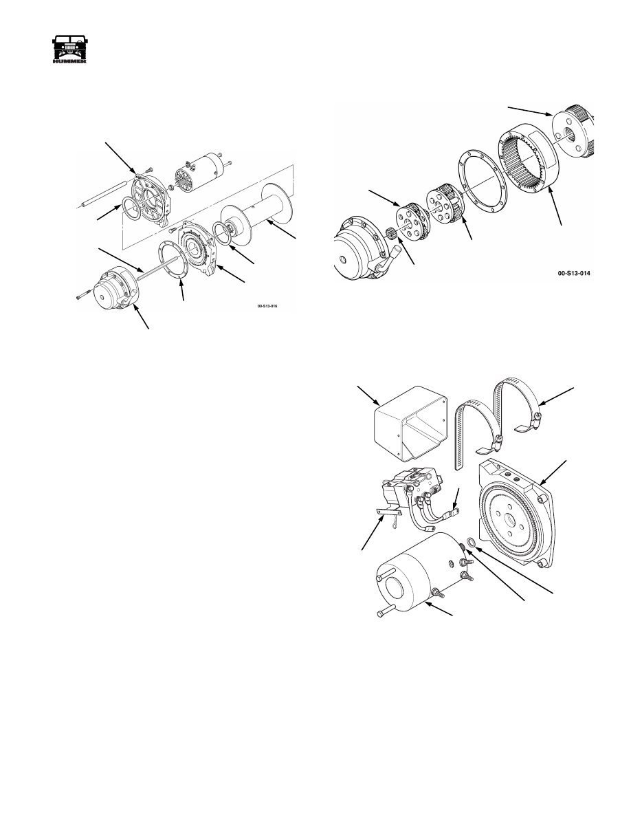
Inspect drum for damage to splined end flanges and tube
(Figure 13-12). Replace winch if damaged.
Figure 13-12: Drum Assembly and Gear Housing
Assembly
2.
Inspect gear end and motor end drum supports for damage.
Replace if damaged.
3.
Inspect gear housing for damage. Replace if damaged.
4.
Inspect thrust plate for damage or wear. Replace if
damaged or worn. Apply grease on thrust plate for
assembly.
5.
Inspect clutch lever and driveshaft for damage. Replace if
damaged.
6.
Inspect gear teeth and machined surfaces of intermediate
ring gear for damage. Replace if damaged.
7.
Inspect gear teeth, splines, and machined surfaces of
output ring gear, output gear carrier, intermediate gear
carrier, and input gear carrier assembly for damage.
Replace any damaged parts (Figure 13-13).
Figure 13-13: Gear Carriers
8.
Inspect brake assembly for damage (Figure 13-18).
9.
Inspect motor, spline, mating surface, and terminals for
damage. Replace motor if damaged (Figure 13-14).
Figure 13-14: Motor and Control Unit
10. Inspect cover for damage. Replace if damaged.
11. Inspect control for damaged leads and damaged mounting
base. Replace control if damaged.
MOTOR END
DRUM SUPPORT
DRUM
GEAR END
DRUM SUPPORT
DRIVE
SHAFT
GEAR
HOUSING
GASKET
THRUST
WASHER
THRUST
WASHER
OUTPUT
RING GEAR
OUTPUT
GEAR CARRIER
INTERMEDIATE
GEAR CARRIER
INPUT
GEAR CARRIER
ASSEMBLY
ASSEMBLY
(THIRD STAGE)
ASSEMBLY
(SECOND STAGE)
(FIRST STAGE)
SUN
GEAR
00-S13-007
COVER
LEAD
CONTROL
SPLINE
MOTOR
DRUM
SUPPORT
SPACER
CLAMP
13-6
Accessories
_______________________________________________________________
®
Assembly
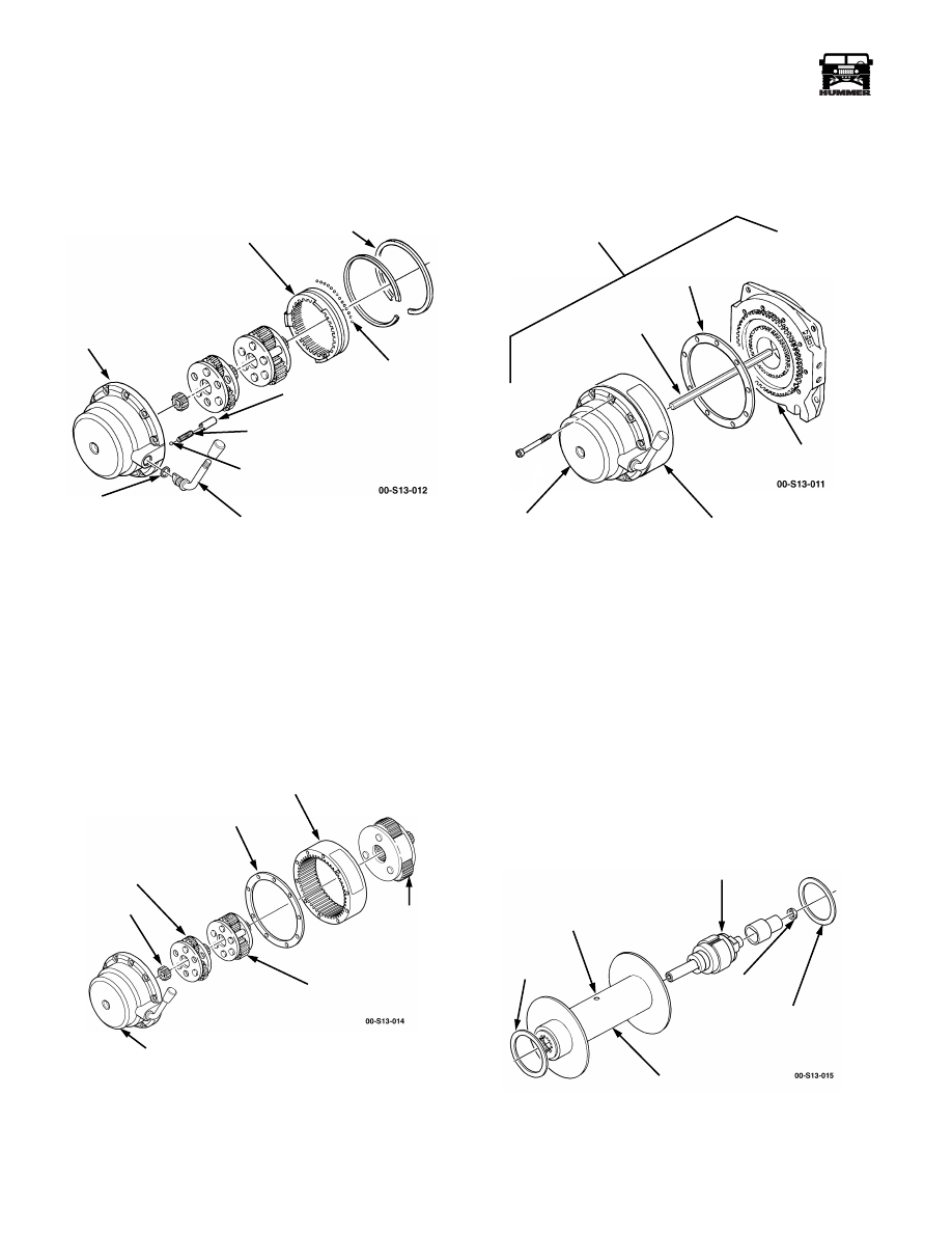
1.
Position 85 to 87 steel balls in groove of intermediate ring
gear and install intermediate ring gear in gear housing
(Figure 13-15).
Figure 13-15: Intermediate Ring Gear and
Gear Housing
2.
Install retaining rings in gear housing.
3.
Apply light oil to steel balls through the clutch lever hole.
4.
Apply grease to clutch lever hole and install O-ring seal
and clutch lever in gear housing.
5.
Install detent ball, spring, and detent spacer in gear
housing.
6.
Apply aircraft grease to output gear carrier, intermediate
gear carrier, and input gear carrier assembly (Figure 13-16).
Figure 13-16: Gear Carriers
7.
Install input gear carrier assembly in gear housing.
NOTE:
Be sure ring gear engages in gear housing.
8.
Install gasket and output ring gear on gear housing.
9.
Install intermediate gear carrier on gear housing.
10. Install output gear carrier on intermediate gear carrier.
11. Install gasket on output ring gear (Figure 13-17).
Figure 13-17: Gear Train Assembly
NOTE:
Ensure spline on drum support engages in output ring
gear.
12. Install gear end drum support on output ring gear and gear
housing.
13. Secure gear housing assembly to drum support with ten
socket-head cap screws. Tighten hex-head screws to 100
lb-in. (11 N•m).
14. Turn gear train assembly over with drum support facing
up.
15. Install driveshaft in gear train assembly (Figure 13-17).
16. Apply grease to drum bushings, seals, and output spline.
Figure 13-18: Thrust Washers and Brakes
O- RING
CLUTCH
LEVER
DETENT
BALL
SPRING
DETENT
SPACER
INTERMEDIATE
RING GEAR
RETAINING
RING
STEEL
BALLS
GEAR
HOUSING
SEAL
OUTPUT
GEAR
OUTPUT
RING GEAR
INTERMEDIATE
GEAR CARRIER
GASKET
INPUT
GEAR CARRIER
ASSEMBLY
GEAR
HOUSING
SUN
GEAR
CARRIER
GEAR TRAIN
ASSEMBLY
GASKET
DRIVE
SHAFT
GEAR END
DRUM SUPPORT
OUTPUT
RING GEAR
GEAR
HOUSING
NYLON THRUST
WASHER
BRAKE
DRUM
NYLON THRUST
WASHER
SET SCREW
BRAKE RETENSION
NOT REMOVABLE
TOLERANCE
RING
ASSEMBLY
______________________________________________________________
Accessories 13-7
®
05745159
17. With drum horizontal, install brake into drum
(Figure 13-18).
18. Tighten brake retaining set screw to 18-22 ft-lb (24-30
N•m) torque.
19. Install two nylon thrust washers on drum.
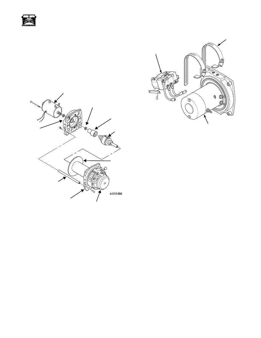
20. Install drum assembly on gear train assembly. Rotate drum
assembly as needed to engage driveshaft, brake, and
output spline (Figure 13-19).
Figure 13-19: Drum Assembly and Gear
Train Assembly
21. Install brake drive and spacer to motor shaft.
22. Install motor end drum support on drum assembly.
23. Install motor on motor end drum support, ensuring to
engage brake drive with brake shaft end.
24. Install three tie rods between drum supports and secure
with six bolts. Tighten bolts to 18 lb-ft (24 N•m).
Figure 13-20: Control Unit and Motor
25. Connect three control leads to terminals and secure with
nuts (Figure 13-21).
26. Secure control to motor with clamps (Figure 13-20).
27. Install winch assembly and winch cable.
Winch Electric Thermal Switch/Brush
Assembly Replacement
Removal
1.
Remove winch and winch cable.
NOTE:
Tag leads for assembly.
2.
Remove three nuts and control leads from motor
(Figure 13-21).
3.
Loosen clamps and remove control from motor
(Figure 13-22).
MOTOR, 12 VDC
SHOWN WITHOUT CONTROL
SPACER (2)
DRUM SUPPORT
BRAKE
BRAKE
DRUM
ASSEMBLY
DRIVER
MOTOR END
DRUM SUPPORT
MOTOR END
TIE ROD
GEAR TRAIN
ASSEMBLY
00-S13-006
CONTROL
CLAMP
MOTOR

13-8
Accessories
_______________________________________________________________
®
Figure 13-21: Control Leads
Figure 13-22: Control Unit and Motor
4.
Remove clamps from motor.
5.
Place winch on end with motor end up (Figure 13-25).
6.
Remove two bolt assemblies and rear cover from motor
housing.
NOTE:
Perform steps 7 through 11 only if replacing brush as-
sembly.
7.
Remove electric thermal switch from two electric thermal
switch leads.
8.
Remove motor housing from drum support and armature
assembly from brush assembly (Figure 13-24).
9.
Remove nut, lockwasher, washer, and insulator securing
brush assembly power stud to motor housing. Discard
lockwasher.
10. Remove three nuts, screws, and brush assembly from
motor housing.
11. Remove spacer, insulator, and washer from brush
assembly power stud.
Figure 13-23: Motor and Gasket
Installation
NOTE:
Do not apply coating to any electrical contacts of the
armature assembly. Perform steps 1 through 5 only if replacing
brush assembly.
1.
Install washer, insulator, and spacer on brush assembly
power stud (Figure 13-24).
2.
Install brush assembly in motor housing with three screws
and nuts
.
Figure 13-24: Brush Assembly and Armature
Assembly
00-S13-005
CLAMP
DRUM SUPPORT
NUT
MOTOR
CONTROL
LEAD
TERMINAL
CONTROL
00-S13-009
MOTOR
CLAMP
SPACER
DRUM SUPPORT
CONTROL
REAR COVER
SPACER
ELECTRIC THERMAL
SWITCH
ELECTRIC THERMAL
SWITCH LEADS
MOTOR
HOUSING
BOLT
ASSEMBLY
SPACER
MOTOR
HOUSING
ARMATURE
ASSEMBLY
BRUSH
BRUSH
POWER
ASSEMBLY
ASSEMBLY
STUD
Нет комментариевНе стесняйтесь поделиться с нами вашим ценным мнением.
Текст