Hummer H1 (2002+). Manual — part 254
______________________________________________________________
Accessories 13-9
®
05745159
3.
Secure brush assembly power stud to motor housing with
insulator, washer, lockwasher, and nut.
4.
Coat armature shaft with lubricant and install in brush
assembly.
5.
Coat head of electric thermal switch with lubricant and
connect to two electric thermal switch leads
(Figure 13-23).
6.
Position spacer in drum support, and install rear cover on
motor housing.
7.
Install motor on drum support ensuring to engage motor
shaft into brake drum.
8.
Secure motor to motor end drum support with two bolt
assemblies. Tighten hex-head bolt to 60-70 lb-in. (7-8
N•m) (Figure 13-25).
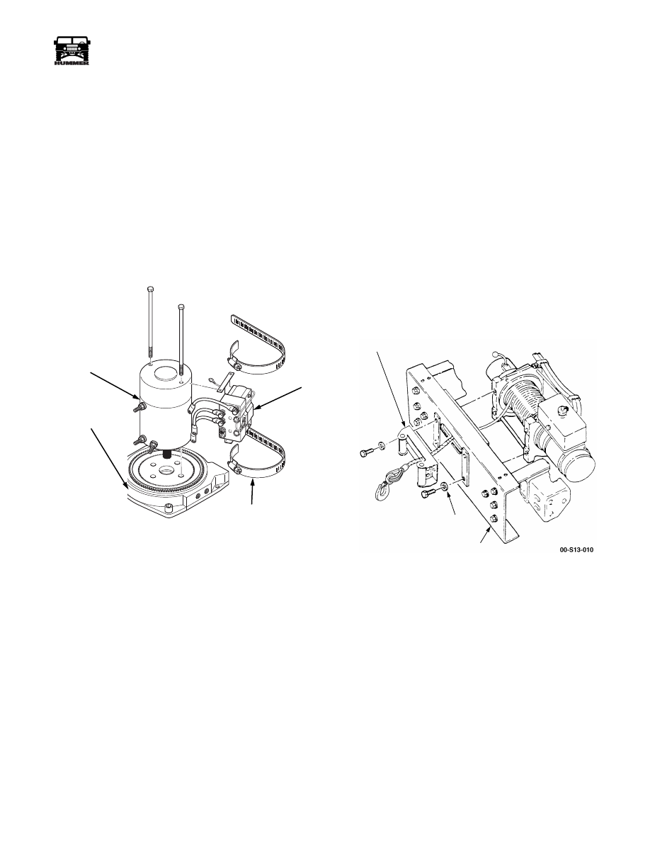
Figure 13-25: Control Unit and Motor
9.
Install clamps on motor.
10. Install control on motor.
11. Connect three control leads to terminals and secure with
nuts (Figure 13-21).
12. Secure control to motor with clamps.
13. Install winch assembly and winch cable.
Winch Roller Fairlead (Option)
Replacement
The winch roller fairlead provides greater functional versatil-
ity. The winch cable can be routed at much sharper angles
since the fairlead rollers will keep it from binding on the
bumper edges.
Removal
WARNING: To avoid injury or damage, support winch
during removal.
1.
Remove circlips on one vertical and one horizontal roller.
2.
Remove one vertical and one horizontal roller.
3.
Remove washers, bolts, and the roller fairlead from the
front bumper (Figure 13-26).
Figure 13-26: Winch Fairlead
Installation
1.
Place the winch cable and hook assembly through the
roller fairlead and install the fairlead on the front bumper
with washers and bolts. Tighten bolts to 60 lb-ft (81 N•m)
(Figure 13-26).
2.
Install the horizontal and vertical rollers and circlips.
00-S13-008
MOTOR
MOTOR END
DRUM SUPPORT
CLAMP
CONTROL
FAIRLEAD
WASHER
FRONT
BUMPER
13-10
Accessories
_____________________________________________________________
®
BRUSHGUARD ASSEMBLY REPLACEMENT
NOTE:
Brushguard assemblies may be used on vehicles with
or without a winch assembly. The following procedure applies
to vehicles without a winch assembly.
Removal
WARNING: Stand clear of brushguard after removal
of locking pins. Brushguard may swing down, causing
personal injury.
1.
Remove two locking pins from support brackets and lower
brushguard.
2.
Remove two locknuts, washers, bolts, washers, and
brushguard from support brackets.
3.
Remove four locknuts, washers, bolts, washers, and two
support brackets from bumper.
Installation
1.
Install two support brackets on bumper with four washers,
bolts, washers, and locknuts. Tighten locknuts to 68 lb-ft
(92 N•m) (Figure 13-27).
2.
Position brushguard in brackets and secure with two
washers, bolts, washers, and locknuts.
3.
Secure brushguard in upward position with two locking
pins.
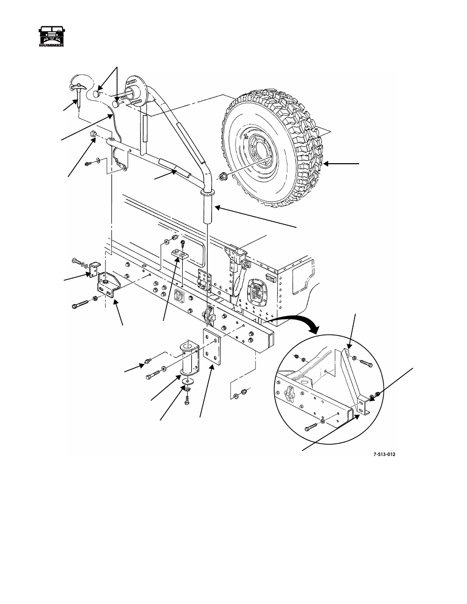
SWING-AWAY SPARE TIRE CARRIER
REPLACEMENT
Removal
WARNING: Support tire when removing lug nuts. The
spare tire and wheel assembly weighs approximately
150 lbs (68 kg) and personal injury may result if the as-
sembly is not properly supported.
1.
Remove lug nuts and wheel/tire assembly from frame
assembly (Figure 13-28).
2.
Remove self-tapping screw and washer securing lanyard
to frame and remove lanyard and lock pin.
3.
Remove self-tapping screws and guide block from rear
bumper.
4.
Remove locknuts, washers, bolts, and stop bracket from
rear bumper.
5.
Remove bolts, washers, and hold-down bracket from stop
bracket.
6.
Remove bolt, washer, and retaining plate from mounting
bracket.
7.
Remove frame assembly from mounting bracket.
8.
Remove end caps from frame assembly.
9.
Remove locknuts, washers, spacer, bolts, washers, and
mounting bracket from rear bumper.
10. Remove grease fitting from mounting bracket.
Figure 13-27: Brushguard Assembly
BUMPER
BRUSHGUARD
SUPPORT
LOCKING
BRACKET
PIN
____________________________________________________________
Accessories 13-11
®
05745159
Figure 13-28: Swing-Away Spare Tire Carrier Breakdown
LOCK
END CAPS
RUBBER
WHEEL/TIRE
FRAME ASSEMBLY
LANYARD
END
GUIDE
HOLD-DOWN
STOP
ANGLED
BUMPER
SQUARED
SPACER
CUSHION
SIDE
BRACE
SIDE
BRACKET
BLOCK
BRACKET
RETAINING
PLATE
GREASE
FITTING
BRACKET
ASSEMBLY
PIN
CAP
ASSEMBLY
13-12
Accessories
_____________________________________________________________
®
Installation
1.
Install grease fitting in mounting bracket (Figure 13-28).
2.
Attach mounting bracket and spacer to rear bumper with
bolts, washers, and locknuts. Raise mounting bracket to
highest position possible and tighten nuts to 90 lb-ft (122
N•m).
3.
Secure guide block on rear bumper with self-tapping
screws.
4.
Attach hold-down bracket to stop bracket with washers,
and bolts. Do not tighten.
5.
Attach stop bracket to rear bumper with bolts, washers,
and locknuts. Do not tighten.
6.
Lubricate frame assembly. Slide frame assembly into
mounting bracket and fasten with bolt, washer and
retaining plate.
7.
Push three end caps into open ends of frame assembly.
8.
Adjust the stop and hold-down brackets that were
previously installed.
a.
Set frame assembly in locked position so that it rests
on bumper guide block. If weight of frame assembly
does not rest on guide block, lower mounting bracket
until it does.
b.
Insert locking pin through frame assembly and into
stop bracket.
c.
Mark position of stop bracket.
d.
Move frame assembly out of the way and tighten stop
bracket assembly securely.
e.
Move frame assembly back to locked position and
align hold-down bracket as close to frame assembly
as possible.
f.
Tighten hold-down bracket securely.
9.
Secure lanyard assembly to frame assembly with washer
and self-tapping screw.
10. Apply cushion tape to frame assembly on surfaces closest
to rear of vehicle body.
11. Install lock pin in frame assembly.
12. Secure wheel/tire assembly to frame assembly with lug
nuts.
13. Lubricate mounting bracket with multi-purpose grease
using the grease fitting.
Нет комментариевНе стесняйтесь поделиться с нами вашим ценным мнением.
Текст