Hummer H1 (2002+). Manual — part 42
___________________________________________
Fuel, Emissions, and Exhaust 3-29
®
5745159
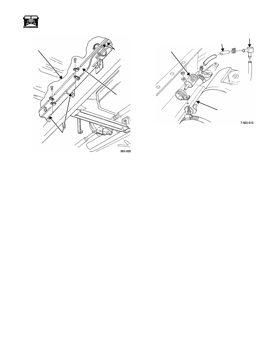
Figure 3-37: Fuel Tank Vent Line Locations
(Typical)
Fuel Tank Vent Line Service
Removal
1.
Remove fuel tank. Refer to procedure in this section.
2.
Remove clip and fuel tank vent line hose from vent line
(Figure 3-37).
3.
Remove vent line clamps and disenagage lines.
4.
Remove tie strap securing vent line to fuel lines. Discard
tie strap.
5.
Disconnect fuel tank vent lines at tank fittings.
Installation
1.
Connect vent lines to tank fitting.
2.
Secure vent line to fuel lines with new tie strap (Figure 3-37).
3.
Secure vent lines in brackets with clamps and bolts.
4.
Install fuel tank.
FUEL TANK VENT FILTER REPLACEMENT
The fuel tank vent filter is located just above the surge tank at
the passenger side of the engine compartment (Figure 3-37).
The filter is serviced as an assembly and should be replaced if
restricted or damaged.
To replace the filter, remove the filter retaining clamp bolt, pull
the filter out of the clamp, and disconnect it from the vent line.
Be sure the replacement filter is properly secured in the clamp
afterward. Also, use a new vent line clamp if the original is
worn, or distorted.
Figure 3-38: Fuel Tank Vent Filter Location
MAIN OR AUXILIARY TANK FUEL LINE
REPLACEMENT (ALL)
Removal
1.
Drain tank with portable, air powered equipment.
2.
Remove main or auxiliary fuel tank as described in this section.
3.
Disconnect any electrical wires, linkage parts, cables, or
lines as needed if insufficient slack exists.
4.
Disconnect fuel lines at main tank tubes.
5.
Remove line clamps and tie straps.
6.
Disconnect lines at fuel tank selector valve and remove
lines.
7.
Disconnect supply line at fuel pump.
8.
On all models, if front lines are to be replaced, disconnect
lines at fuel pump and return fittings.
9.
Remove supply and/or return lines as needed
(Figure 3-39).
Installation
1.
Route new lines as needed (Figure 3-39). Be sure lines are
not kinked, pinched, or touching hot or rotating parts.
2.
Connect front fuel lines to fuel pump and return fitting at
injection pump. Then connect lines to fuel selector valve.
3.
Secure lines to frame clamps, brackets, P-clips, and tie
straps as needed.
4.
Connect rear lines to auxiliary or main tank as required.
5.
Install main or auxiliary fuel tank as described in this
section.
6.
Verify that fuel lines are securely connected and properly
routed.
7.
Refill fuel tank.
8.
Check tank operation. Verify proper transmitter operation
and selector switch function.
FUEL TANK
VENT LINE
FUEL LINES
VENT LINE
BRACKETS
VENT LINE FILTER
FUEL TANK
VENT LINE
ELBOW
BODY
BRACKET
3-30
Fuel, Emissions, and Exhaust
___________________________________________
®
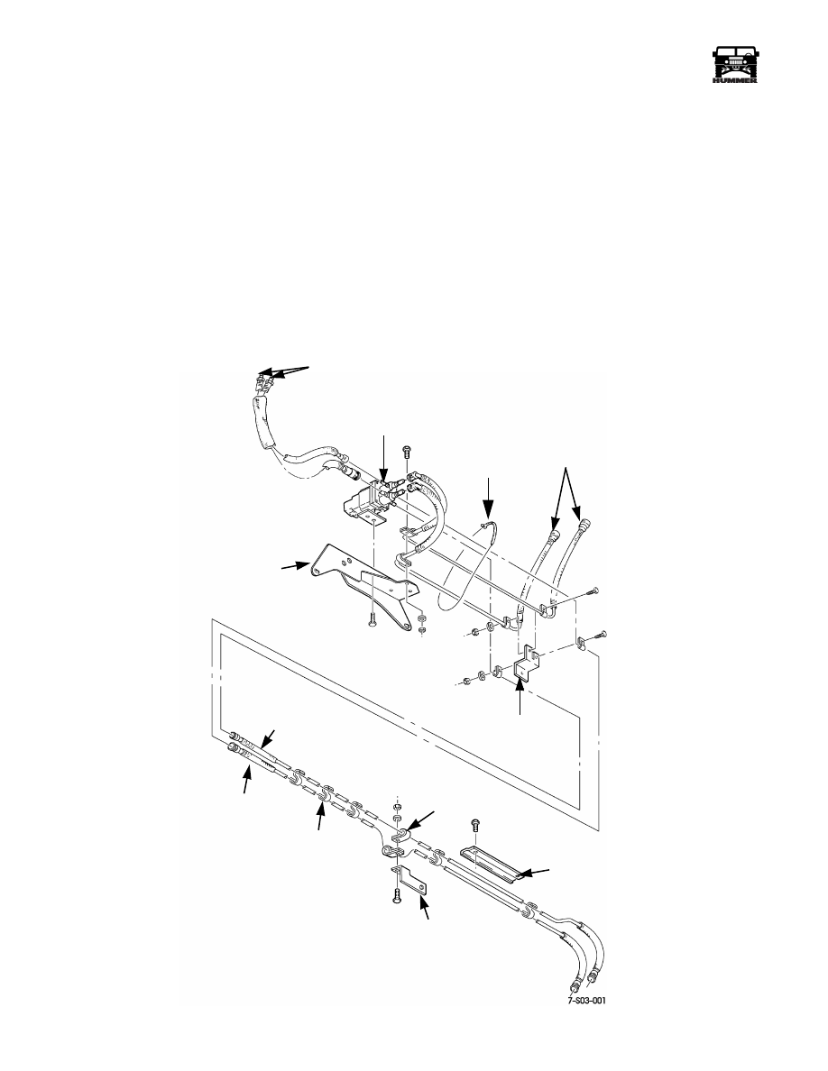
FUEL SELECTOR VALVE
The selector valve is used on models equipped with an auxil-
iary fuel tank (Figure 3-39). The valve is electrically operated
by a switch in the passenger compartment. The switch will be
mounted on the instrument panel.
Valve function is to switch fuel supply from main to auxiliary
tank (and back) when needed.
Quick connect fittings are used to attach each of the six fuel
lines to the valve. The plastic, two-piece style fittings are used.
The valve is mounted on a bracket attached to the passenger
side frame rail. Valve position is forward of the fuel tank and
B-pillar area.
The valve is not a serviceable part and must be replaced when
diagnosis indicates this is necessary.
Selector Valve Replacement
The valve is accessible from under the vehicle. Disconnect the
battery and remove the valve-to-bracket bolts first. Then dis-
connect the fuel lines one at a time and tag them for reference.
Last, disconnect the valve-to-switch harness and remove the
valve. Reverse the process to install the valve.
Figure 3-39: Fuel Lines, Connections, and Attachment
VALVE
MOUNTING
BRACKET
RETURN LINE
(AUXILIARY TANK)
CLAMP
(TYPICAL)
FUEL LINE
BRACKET
FUEL LINE
BRACKET
S-CLIP
(TYPICAL)
SUPPLY LINE
(AUXILIARY TANK)
VALVE-TO-PUMP
AND INJECTOR LINES
FUEL SELECTOR VALVE
TANK-TO-VALVE
LINES
FUEL LINE
BRACKET
TIE STRAP
___________________________________________
Fuel, Emissions, and Exhaust 3-31
®
5745159
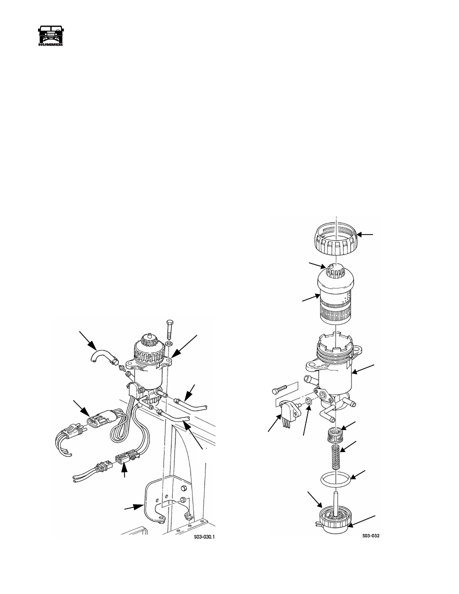
FUEL FILTER SERVICE
Fuel Filter Replacement
Removal
1.
Loosen the hose clamps securing the CTIS compressor (if
equipped) to its mounting bracket and slide the compres-
sor forward to gain access to the fuel filter.
2.
Disconnect fuel inlet and outlet hoses from filter
(Figure 3-40:).
3.
Disconnect drain hose from fuel filter.
4.
Disconnect filter harness connectors.
5.
Remove filter attaching bolts and remove fuel filter from
bracket.
Disassembly
1.
Remove retaining nut and filter element from header.
2.
Remove sensor and O-ring.
3.
Loosen cap nut and remove fuel heater, seal, spring, and
screen.
Assembly
1.
Install screen, spring, cap seal, and fuel heater and tighten
cap nut.
2.
Install O-ring and sensor.
3.
Install filter element and retaining nut.
Figure 3-40: Fuel Filter Mounting
Installation
1.
Install fuel filter on bracket and secure with washers and
bolts (Figure 3-40:).
2.
Connect sensor and fuel heater harnesses to body harness
connectors.
3.
Connect drain hose to fuel filter.
4.
Connect inlet and outlet hoses to fuel filter.
5.
Slide the CTIS compressor rearward into place and tighten
the hose clamps securing the compressor to the mounting
bracket.
Purging Air From Fuel Filter
1.
Loosen fuel filter air bleed valve one-half turn (Figure 3-41).
2.
Run engine until fuel exits from air valve.
3.
Tighten air valve.
Figure 3-41: Fuel Filter Components
FUEL FILTER
OUTLET HOSE
BRACKET
INLET HOSE
DRAIN
HOSE
SENSOR HARNESS
MOUNTING
FUEL HEATER
HARNESS
NUT
ELEMENT
FILTER
SENSOR
O-RING
FUEL HEATER
SPRING
CAP NUT
CAP SEAL
FILTER
AIR BLEED
VALVE
HOUSING
RETAINING
SCREEN
ELEMENT
(WATER IN
FUEL)

3-32
Fuel, Emissions, and Exhaust
___________________________________________
®
Fuel Filter Drain Hose and Valve Replace-
ment
NOTE: To remove fuel filter drain valve only, perform steps 3
and 4.
Removal
1.
Disconnect fuel filter drain hose from fuel filter
(Figure 3-42).
2.
Remove two tie straps and separate drain hose from
transmission oil cooler lines.
3.
Remove two tie straps and separate drain hose from
transmission oil cooler lines.
4.
Disconnect drain hose at drain valve.
5.
Remove nut and drain valve from body
Installation
1.
Install drain valve on body and tighten nut.
2.
Connect drain hose to valve.
3.
Connect drain hose to fuel filter.
4.
Secure drain hose to transmission oil cooler lines with two
tie straps.
5.
Start engine and check for leaks.
Figure 3-42: Fuel Filter Drain Hose And Valve Location
FUEL FILTER
FUEL FILTER
DRAIN HOSE
BODY
DRAIN VALVE
TIE STRAPS
TRANSMISSION
OIL COOLER
LINES
Нет комментариевНе стесняйтесь поделиться с нами вашим ценным мнением.
Текст