Hummer H1 (2002+). Manual — part 43
___________________________________________
Fuel, Emissions, and Exhaust 3-33
®
5745159
FUEL LIFT PUMP SERVICE
Fuel Lift Pump Replacement
Removal
1.
Disconnect fuel pump wiring harness (Figure 3-43).
2.
Disconnect fuel pump hoses.
3.
Loosen clamp and remove pump.
4.
Remove adapters and O-rings from fuel pump. Discard O-
rings.
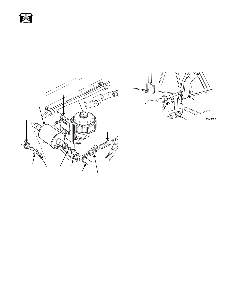
Figure 3-43: Fuel Pump Attachment
Installation
1.
Install O-rings and adapters on fuel pump (Figure 3-43).
Use new O-rings.
2.
Install fuel pump in clamp and tighten clamp securely.
3.
Connect hoses to fuel pump.
4.
Connect wiring harness to pump.
5.
Start engine and check fuel pump and hoses for leaks.
Fuel Tank-To-Filler Neck Hose Replacement
Removal
1.
Drain fuel tank.
2.
Remove filler tube housing bolts.
3.
Disconnect filler tube vent hose.
4.
Loosen clamps and remove hose from tank and filler
(Figure 3-44).
Figure 3-44: Filler Tube-To-Tank Attachment
Installation
1.
Install hose on tank and filler tube and tighten hose
clamps.
2.
Install filler tube and housing.
3.
Fill fuel tank and check for leaks.
00-S13-003
WIRING
HARNESS
BRACKET
HOSE
FUEL
PUMP
O-RING
HOSE
CONNECTOR
ADAPTER
ADAPTER
FILLER TUBE
TANK
FILLER TUBE
-TO-
TANK HOSE
INLET
TUBE
3-34
Fuel, Emissions, and Exhaust
___________________________________________
®
Diesel Injection Pump Fuel Hose or Tube Replacement
Removal
1.
Remove supply hose.
2.
Remove return hose from injection pump and tube
(Figure 3-45).
3.
Remove tube-to-injector hose.
4.
Remove injector connecting hoses (Figure 3-46).
5.
Remove nozzle cap from rear nozzle nipple.
Installation
1.
Install cap on rear injector nipple (Figure 3-46).
2.
Install injector connecting hose.
3.
Install tube-to-injector hose (Figure 3-45).
4.
Install fuel return hoses on tube and injection pump.
5.
Install supply hose.
6.
Start engine and check for fuel leaks.
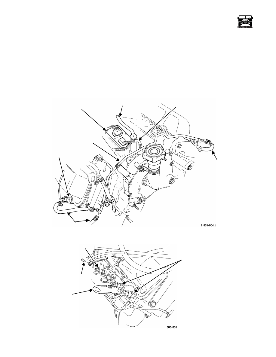
Figure 3-45: Diesel Fuel Injection Return Hose and Tube Routing
Figure 3-46: Injector-To- Injector Return Hose Connection
DRAIN RETURN
HOSE
INJECTION PUMP
INJECTOR
RETURN HOSES
RETURN TUBE
RETURN HOSE
SUPPLY HOSE
CONNECTING
HOSE (TYPICAL)
INJECTORS
CAP
NIPPLE
___________________________________________
Fuel, Emissions, and Exhaust 3-35
®
5745159
GLOW PLUG SERVICE
Glow Plug Tip Removal
(Damaged or Broken)
1.
Remove fuel injector from necessary cylinder.
2.
Using torsional damper bolt (Figure 3-47),rotate crankshaft
to bring affected piston to TDC position.
3.
Using pliers, reach through injector nozzle port
(Figure 3-48), break off expanded tip, and remove from
prechamber.
4.
Remove glow plug.
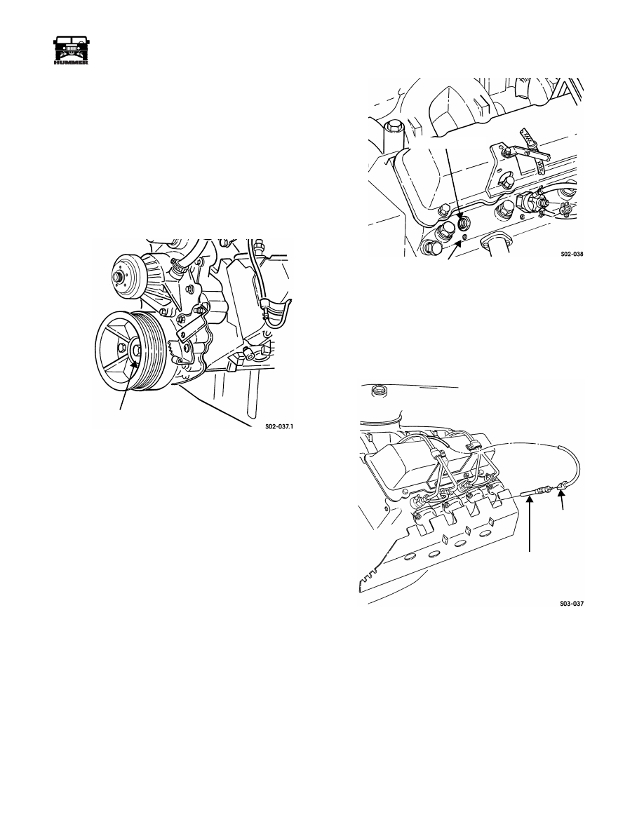
Figure 3-47: Torsional Damper Bolt Location
5.
Direct stream of low-pressure compressed air into glow
plug port. This will expel any remaining pieces of broken
tip through injector port.
NOTE: If the preceding methods fail to remove glow plug tip
remains from the prechamber, the cylinder head must be re-
moved to clear the broken pieces.
6.
Install new glow plug.
7.
Install fuel injector.
Figure 3-48: Glow Plug and Injector Port Locations
Glow Plug Replacement
Removal
1.
Disconnect wire from glow plug with tool J–39083.
2.
Remove glow plug from cylinder head (Figure 3-49).
Figure 3-49: Glow Plug Removal/Installation
Installation
1.
Install glow plug in cylinder head. Tighten plug to 8-12 lb-
ft (11-16 N•m) torque.
2.
Connect wire to glow plug.
TORSIONAL DAMPER BOLT
GLOW PLUG PORT
INJECTOR PORT
GLOW PLUG
WIRE
3-36
Fuel, Emissions, and Exhaust
___________________________________________
®
DIESEL FUEL INJECTION SYSTEM
Diesel Injection Line Bracket And Clamp
Removal
1.
Remove console and engine covers.
2.
Remove air horn.
3.
Remove bracket (Figure 3-50).
4.
Remove bracket from valve cover studs.
5.
Remove line clamps if necessary.
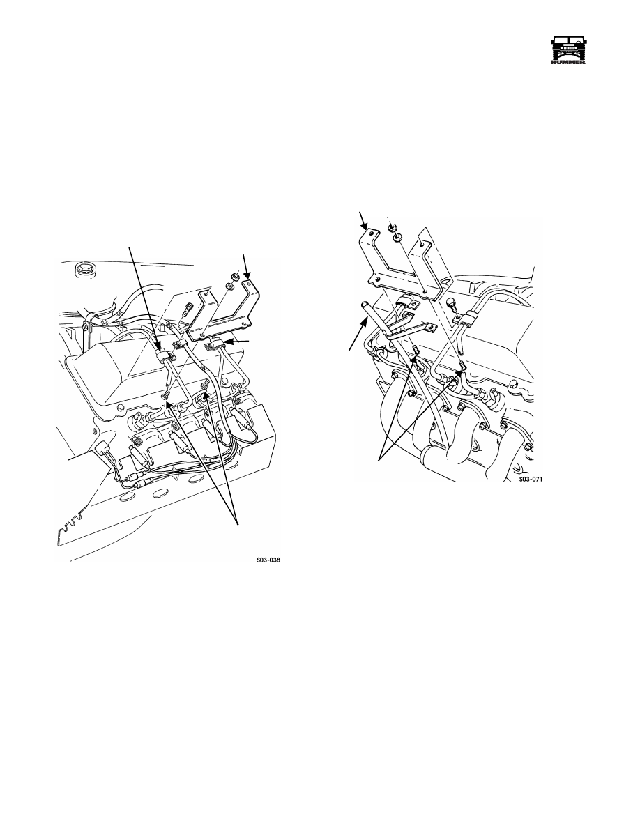
Figure 3-50: Injection Line Bracket Removal/
Installation
Installation
1.
Install clamps on lines if removed.
2.
Install bracket on valve cover studs (Figure 3-51). Tighten
bracket nuts to 13-20 lb-ft (18-27 N•m).
3.
Install air horn.
4.
Install console and engine cover.
Figure 3-51: Injection Line Bracket Removal/
Installation (Driver-Side)
VALVE COVER
STUDS
INJECTOR
LINE
BRACKET
LINE CLAMP
LINE
CLAMP
VALVE COVER
STUDS
INJECTOR
LINE
BRACKET
OIL
DIPSTICK
TUBE
Нет комментариевНе стесняйтесь поделиться с нами вашим ценным мнением.
Текст