Jaguar XJ (X350). Manual — part 766
PINPOINT TEST G552799p1 : GLOW
PLUG CONTROL MODULE (GPCM)
CONTROL CIRCUIT
G552799t1 : CHECK THE GPCM CONTROL CIRCUIT FOR SHORT CIRCUIT TO
GROUND
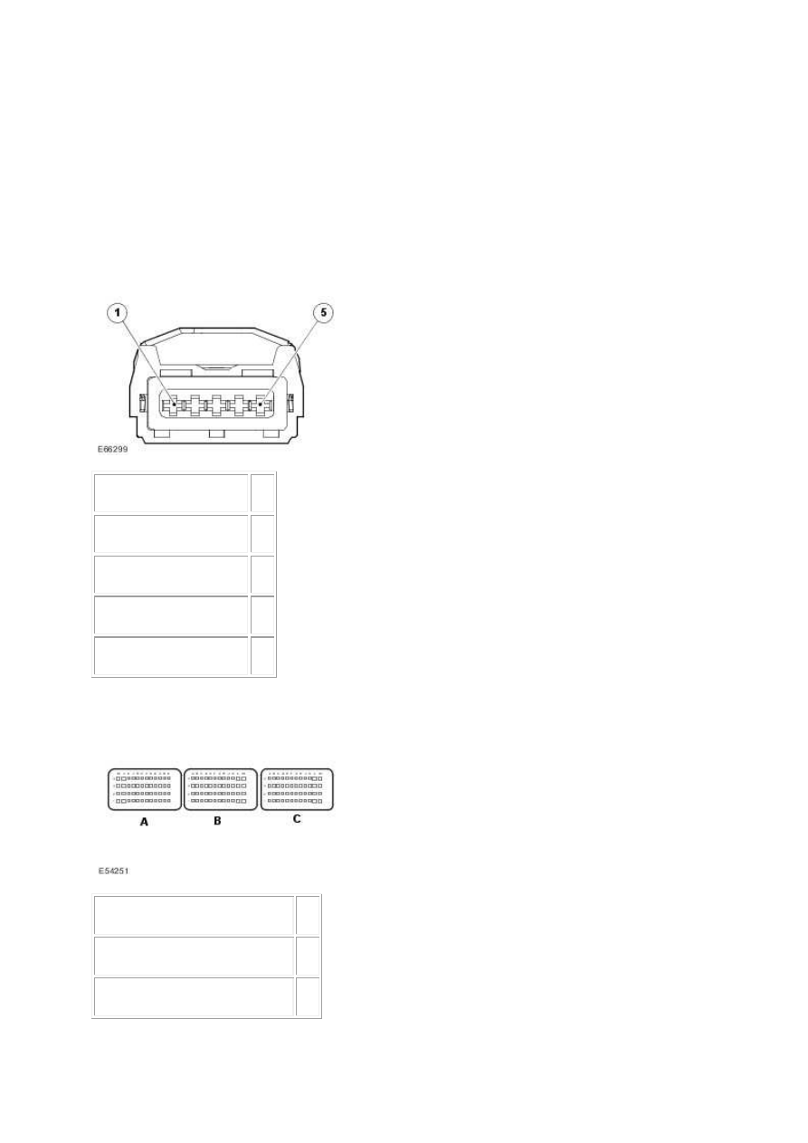
1.
Circuit
Pin
Ground
01
Control from ECM
02
Power supply from FPDB 03
Logic monitor
05
2.
Circuit
Pin
Glow plug control module signal G3
Logic monitor
E3

3. Key off. 4. Disconnect the GPCM electrical connector, EC69. 5. Measure the resistance between:
E69, harness side
Battery
Pin 02
Negative terminal
Is the resistance greater than 10 Kohms?
-> Yes
GO to Pinpoint Test G552799t3.
-> No
GO to Pinpoint Test G552799t2.
G552799t2 : CHECK WHETHER THE SHORT CIRCUIT IS IN THE HARNESS OR
THE MODULE
1. Disconnect the ECM connector, C100. 2. Measure the resistance between:
EC69, harness side
Battery
Pin 02
Negative terminal
Is the resistance greater than 10 Kohms?
-> Yes
An intermittent fault may be present in the wiring harness. Visually check for chaffed wires or other
physical damage to the harness.
-> No
REPAIR the short circuit. For additional information, refer to the wiring diagrams. Clear the DTC, test
the system for normal operation.
G552799t3 : CHECK THE GPCM CONTROL CIRCUIT FOR SHORT CIRCUIT TO
POWER
1. Key off. 2. Measure the resistance between:
EC69, harness side
Battery
www.

Pin 02
Positive terminal
Is the resistance greater than 10 Kohms?
-> Yes
GO to Pinpoint Test G552799t5.
-> No
GO to Pinpoint Test G552799t4.
G552799t4 : CHECK WHETHER THE SHORT CIRCUIT IS IN THE HARNESS OR
THE module
1. Disconnect the ECM connector, C100. 2. Measure the resistance between:
EC69, harness side
Battery
Pin 02
Positive terminal
Is the resistance greater than 10 Kohms?
-> Yes
An intermittent fault may be present in the wiring harness. Visually check for chaffed wires or other
physical damage to the harness.
-> No
REPAIR the short circuit. For additional information, refer to the wiring diagrams. Clear the DTC, test
the system for normal operation.
G552799t5 : CHECK THE GPCM CONTROL CIRCUIT FOR HIGH RESISTANCE
1. Disconnect the ECM connector, C100. 2. Measure the resistance between:
EC69, harness side C100, harness side
Pin 02
Pin G3
Is the resistance less than 10 ohms?
-> Yes
An intermittent fault may be present in the wiring harness. Visually check for chaffed wires or other
physical damage to the harness. Refer to the warranty policy and procedures manual if a module is
suspect.
-> No
REPAIR the high resistance circuit. This circuit includes connector, PI41. For additional information,
refer to the wiring diagrams. Clear the DTC, test the system for normal operation.
PINPOINT TEST G552799p2 : GLOW
PLUG CONTROL MODULE (GPCM)
OUTPUT
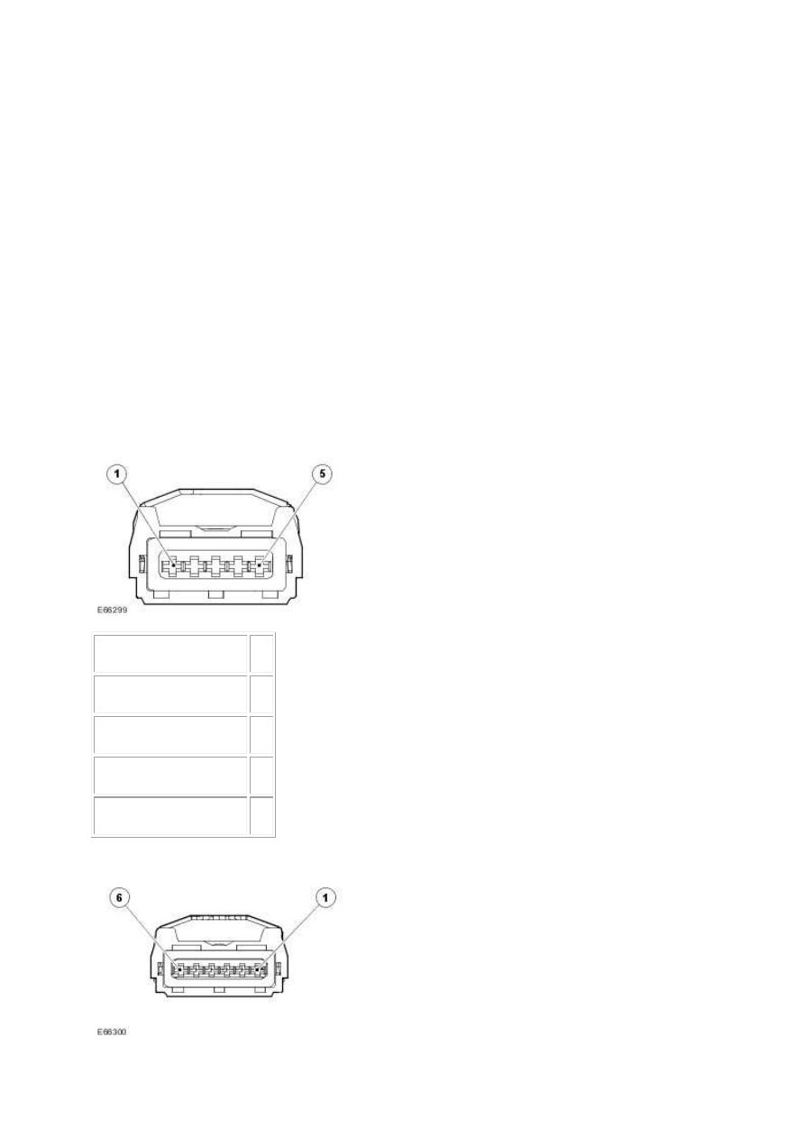
G552799t6 : CHECK THE PERMANENT POWER SUPPLY TO THE GPCM
1.
Circuit
Pin
Ground
01
Control from ECM
02
Power supply from FPDB 03
Logic monitor
05
2.
www.
Нет комментариевНе стесняйтесь поделиться с нами вашим ценным мнением.
Текст