Jaguar XJ (X350). Manual — part 1328
Exterior Lighting - VIN Range: H18680-
>H99999
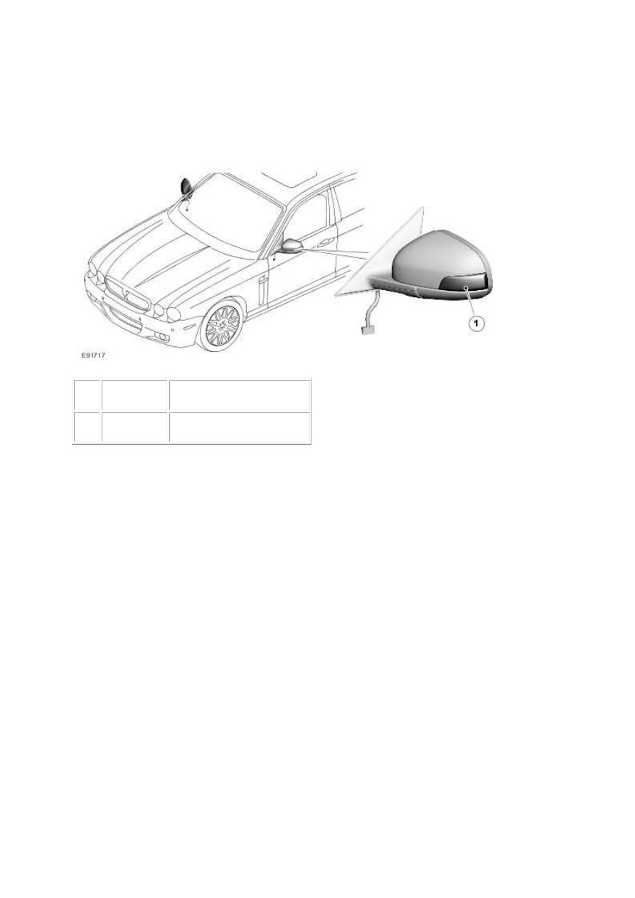
COMPONENT LOCATION
Item
Part Number
Description
1
Direction indicator repeaters
OVERVIEW
Vehicles built from June 2007 feature direction indicator repeaters located in the exterior rear view
mirrors. The functionality and operation of the direction indicator repeaters remains the same as the
previous fender mounted items. For additional information, refer to Exterior Lighting (417-01 )
In the event of a direction indicator repeater bulb failure, the mirror glass will need to be removed.
For additional information, refer to the Owners Handbook.
Vehicles built from June 2007 also feature revised side marker lamps. The revised side marker lamps
also incorporate a reflector.
Item
Part Number
Description
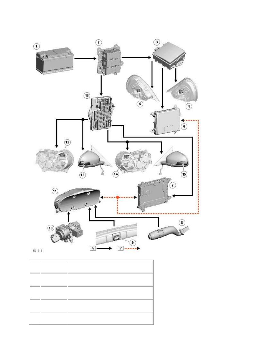
1
Battery
2
Battery junction box
3
Rear power distribution box
4
LH (left-hand) rear direction indicator
CONTROL DIAGRAM
NOTE:
A = Hardwired; Y = SCP (standard corporate protocol) network.
www.

5
RH (right-hand) rear direction indicator
6
REM (rear electronic module)
7
FEM (front electronic module)
8
Lighting switch
9
Hazard warning switch
10
Ignition switch
11
Instrument cluster
12
RH (right-hand) front direction indicator
13
RH (right-hand) direction indicator repeater
14
LH (left-hand) front direction indicator
15
LH (left-hand) direction indicator repeater
16
Passenger junction box
PRINCIPLES OF OPERATION
The direction indicator lamps will only operate when the ignition switch is in position II. An ignition
switch status signal is transmitted to the FEM (front electronic module) from the instrument cluster
on the SCP (standard corporate protocol) network. The hazard warning lamps will operate with the
ignition switch in any position, including off.
Direction Indicators - Front
A battery feed is provided to passenger junction box relays R1A and R1B from a 100 Amp megafuse
located in the BJB (battery junction box) . Relay R1A controls operation of the RH (right-hand)
direction indicators; relay R1B controls operation of the LH (left-hand) direction indicators.
The ground path for both relays coils is controlled by the FEM (front electronic module) . The FEM
(front electronic module) switches the ground path on and off when a request for direction indicator
operation is received from the column switch or the hazard warning switch. The FEM (front
electronic module) receives this request from the instrument cluster over the SCP (standard
corporate protocol) network. When the request for direction indicator operation is withdrawn, the
FEM (front electronic module) removes the ground path from both relay coils.
Direction Indicators - Rear
A battery feed is provided to rear power distribution box relays R8B and R7A. Relay R8B controls
operation of the RH (right-hand) direction indicators; relay R7A controls operation of the LH (left-
hand) direction indicators.
The ground path for both relay coils is controlled by the REM (rear electronic module) . The REM
(rear electronic module) switches the ground path on and off when a request for direction indicator
operation is received from the column switch or the hazard warning switch. The REM (rear electronic
module) receives this request from the instrument cluster over the SCP (standard corporate
protocol) network. When the request for direction indicator operation is withdrawn, the FEM (front
electronic module) removes the ground path from both relay coils.
www.
Нет комментариевНе стесняйтесь поделиться с нами вашим ценным мнением.
Текст