Jaguar XJ (X350). Manual — part 1329
Exterior Lighting – Armoured
Headlamps
The air suspension system has been removed from the armoured vehicle. To prevent the generation of
diagnostic trouble codes (DTC) being logged, the air suspension module has been removed from the vehicle.
The headlamp levelling function is now provided by using a combination of components from X350 (XJ)
04MY, X100 (XK8) and the headlamp module supplier Valeo. The integral headlamp module within each
headlamp receives electrical signals direct from the headlamp levelling sensors that are installed to the
vehicles suspension.
Flashing Headlamps
The flashing headlamp system consists of a luggage compartment mounted alternating flash unit and relay, a
floor console mounted switch and two changeover relays mounted adjacent to the front power distribution
fuse box. The system is integrated into the vehicle with a harness kit.
The electrical feed is via fuse 4 in the luggage compartment mounted auxiliary fuse box. A switch located in
the auxiliary switch panel in the floor console controls the flashing headlamps. With the switch in the on
position, a battery feed is diverted through an alternating flash relay to the halogen "flash to pass" bulbs in
the left and right hand headlamp units.
An electrical feed from the battery positive terminal is supplied on a red (R) wire to the auxiliary fuse box
mounted in the luggage compartment of the vehicle. Fuse 4 provides a feed to the switch headlamp flash and
relay 3 on a purple and blue (PU) wire. With the switch headlamp flash in the ON position a feed is
provided to the coils of 1,2 and 3 on a blue and black (UB) wire. Relay 3 is pulled in and provides a feed to
the alternating flash relay XF003-1 on a white and blue (WU) wire.
The alternating outputs XF004-1 and XF005-1 are connected to relay 1 and relay 2 on a white (W) and a
blue (U) wire respectively, and as relay 1 and relay 2 are pulled in are connected to the left-hand headlamp
unit and right-hand headlamp unit on orange (O) and orange and green (OG) wires respectively. NOTE: A
conventional halogen headlamp bulb (flash to pass) is used for the flashing headlamp feature; the high
intensity discharge headlamp lamp bulb is not operated. Igniting and extinguishing the high intensity
discharge headlamp several times during a small period of time, will cause premature failure of the
headlamp and/or the control module.
Covert Blue Lamps
The covert blue lamps system consists of a luggage compartment mounted alternating flash unit, a floor
console mounted switch and two radiator grille mounted LED lamps. The system is integrated into the
vehicle with a harness kit.
The electrical feed is provided via fuse 6 in the luggage compartment mounted auxiliary fuse box. A switch
located in the auxiliary switch panel in the floor console controls the covert blue lamps. A battery feed is
provided to the Switch on a purple green (PG) wire via fuse 6 of the auxiliary fuse box. With the switch in
the ON position a feed is provided to the alternating flash relay XC003-1 an blue and red (UR) wire. The
alternating outputs XC006-1 and XC005-1 of the flash relay are provided to the left and right LED lamp
units on blue and slate (US) and blue and green (UG) wires respectively.
The LED lamp units are grounded via XC009. The alternating flash unit is grounded via XC010. Switch
illumination is provided on a red and white (RW) wire to XC002-2 and XC002-5 is grounded at XI001. The
LED lamp units are pre-set to display three consecutive pulses per flash at a rate of approximately 83 FPM.
Published: Mar 12, 2014
Vehicles

Diagnosis and testing
Headlamps
Inspection and Verification
1 . Verify the customer concern.
2 . Visually inspect for obvious signs of electrical damage.
Visual Inspection Chart
Electrical
•
Bulb(s)
•
Photocell(s)
•
Ballast
•
Wiring harness/electrical connectors
•
Fuse(s)
1 . If an obvious cause for an observed or reported concern is found, correct the cause (if possible)
before proceeding to the next step.
2 . If the cause is not visually evident, verify the symptom and refer to the Jaguar Approved
Diagnostic System.
www.
Removal and installation
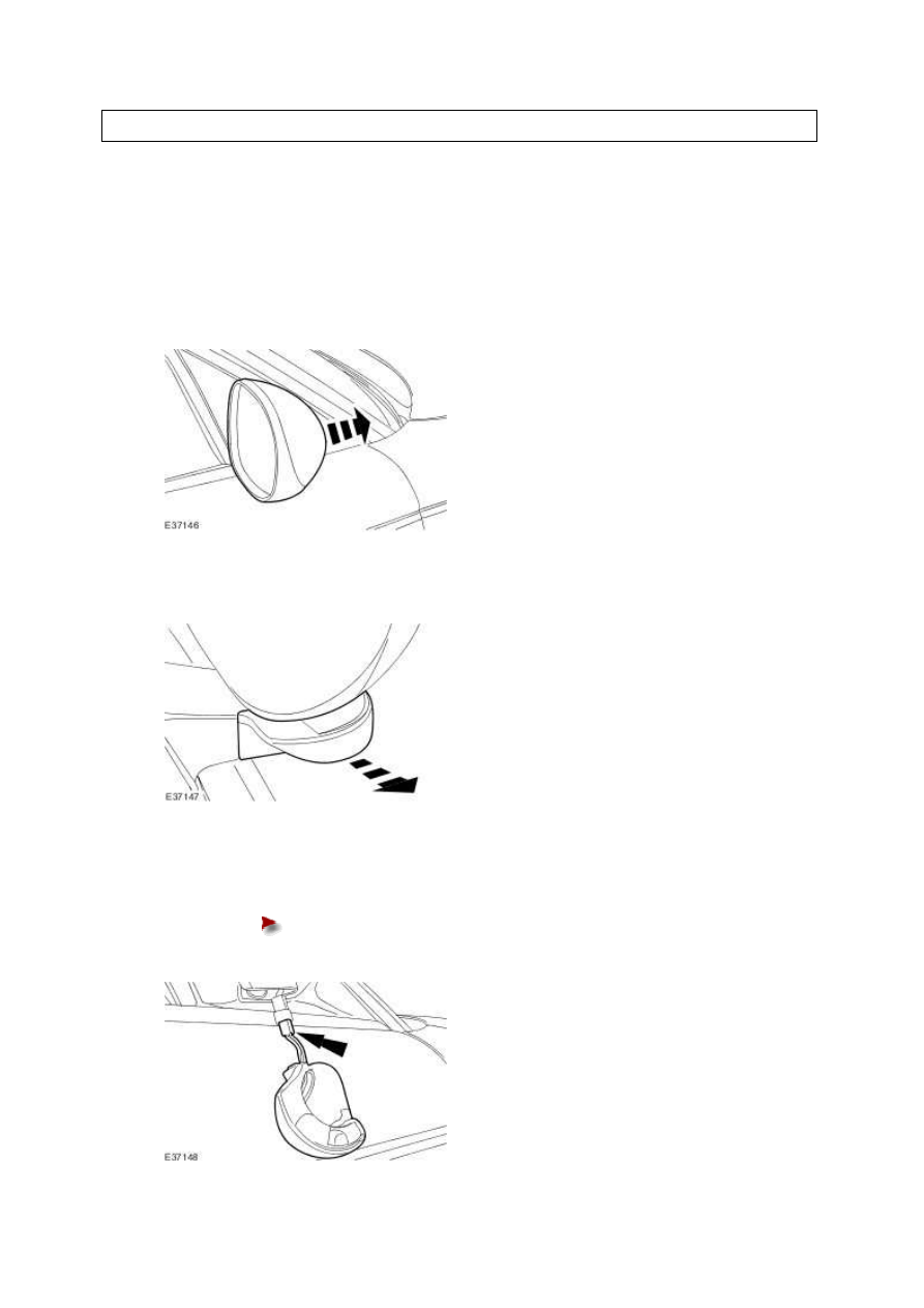
Approach Lamp - VIN Range: G00442-
>H18679
Removal
1 . Reposition the exterior mirror.
2 . Detach the approach lamp.
3 . Remove the approach lamp.
Disconnect the electrical connector.
Installation
1 . To install, reverse the removal procedure.
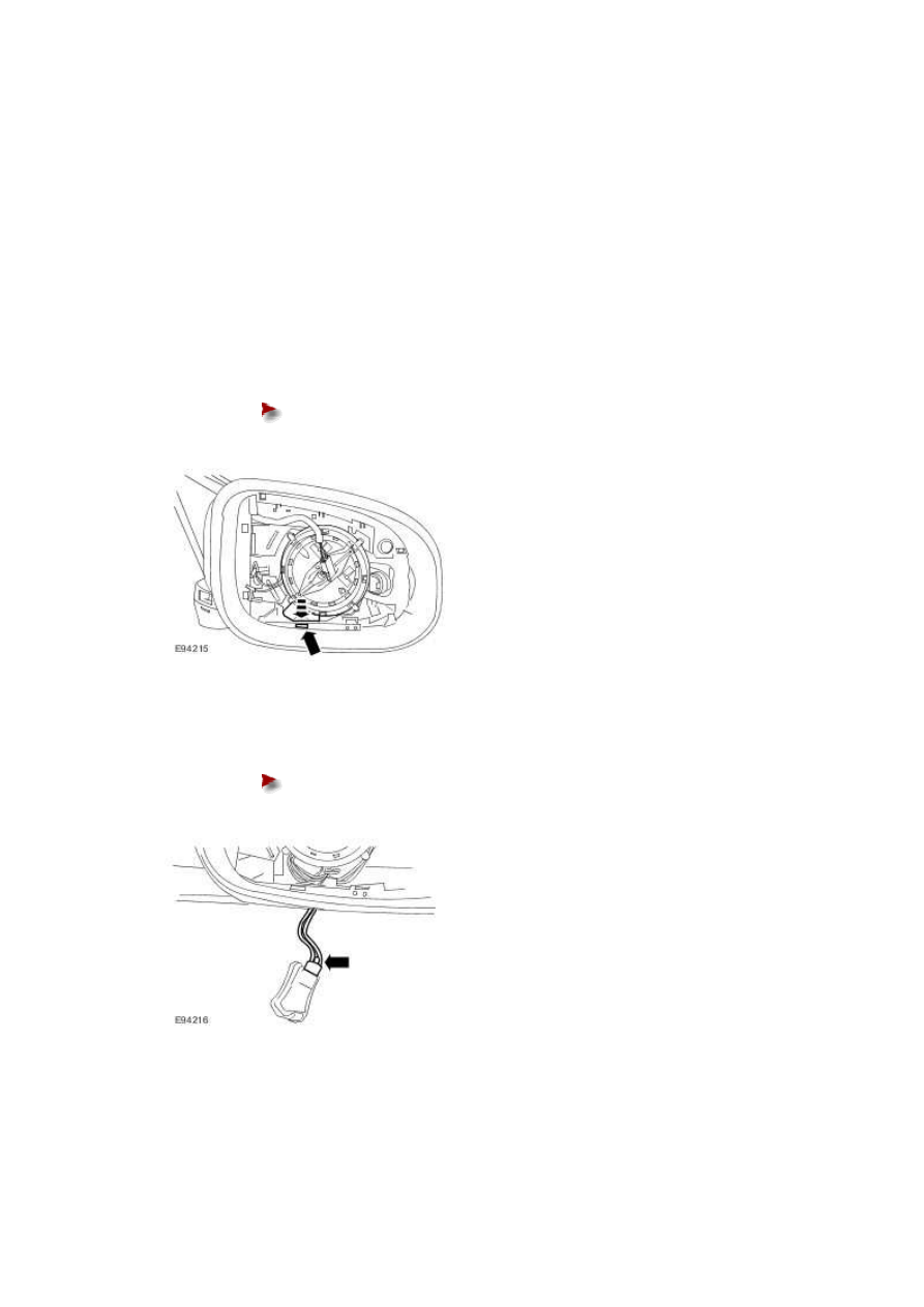
Approach Lamp - VIN Range: H18680-
>H99999
Removal
1 . Remove the exterior mirror glass.
For additional information, refer to Exterior Mirror Glass (76.10.53)
2 . Release and reposition the approach lamp.
Release retaining clip.
3 . Remove the approach lamp.
Disconnect the electrical connector.
Installation
1 . To install, reverse the removal procedure.
www.
Нет комментариевНе стесняйтесь поделиться с нами вашим ценным мнением.
Текст