Jaguar XJ (X350). Manual — part 1255

413-01 : Instrument Cluster
Specifications
Specifications
General specifications
Item
Specification
Illumination bulb. 3.0 Watt
Description and operation
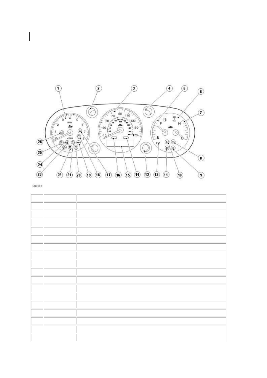
Instrument Cluster
Item Part Number
Description
1
—
Tachometer
2
—
Left-hand direction indicator
3
—
Speedometer
4
—
Right-hand direction indicator
5
—
Fuel gauge
6
—
High engine temperature indicator
7
—
Engine temperature gauge
8
—
Side lamps indicator
9
—
Rear fog lamps indicator
10
—
High beam indicator
11
—
Front fog lamps indicator
12
—
Low fuel level indicator
13
—
Adaptive speed control indicator
14
—
Message center red warning indicator-primary warning
15
—
Message center display
16
—
Message center amber warning indicator-secondary warning
17
—
Low tire pressure warning indicator
www.
18
—
Check engine warning indicator
19
—
Engine oil pressure warning indicator
20
—
Parking brake, low brake fluid indicator
21
—
Battery charge warning indicator
22
—
Traction control/Dynamic Stability Control (DSC) warning indicator
23
—
Anti-Lock Brake System (ABS) warning indicator
24
—
Safety belt warning indicator
25
—
Airbag warning indicator
26
—
Vehicle overspeed warning indicator
The instrument cluster provides the driver with information, indicators and warning indicators
on the vehicle systems.
The gauges and warning indicators may use the outputs from common sensors to carry out
their respective functions.
Instrument Cluster – Armoured
WARNING: Make sure that the correct calibration is programmed into the instrument cluster.
Failure to follow this instruction may result in personal injury.
CAUTION: Make sure that the correct calibration is programmed into the instrument cluster.
Failure to follow this instruction may result in damage to the vehicle.
This vehicle has a unique instrument cluster calibration. If the incorrect instrument cluster
calibration is programmed to the vehicle, the speedometer will display an inaccurate vehicle
speed.
Vehicles
Diagnosis and testing
Instrument Cluster
Principles of Operation
For a detailed description of the Instrument Cluster, refer to the relevant Description and Operation
sections in the workshop manual.
Instrument Cluster
Inspection and Verification
1 . Verify the customer concern.
2 . Visually inspect for obvious signs of mechanical or electrical damage.
Visual Inspection Chart
Electrical
•
Fuses/Relays
•
Damaged, Loose or Corroded Connector(s)
•
Damage to Wiring Loom/Incorrect Location, Stretched or Taught
1 . If an obvious cause for an observed or reported concern is found, correct the cause (if possible)
before proceeding to the next step.
2 . If the cause is not visually evident, verify the symptom and refer to the Jaguar approved diagnostic
system.
3 . If an instrument cluster warning lamp is illuminated, this normally indicates a non instrument
cluster fault. Interrogate the relevant module for stored DTCs and act on this information. When the
repair has been carried out, the fault codes cleared and after cycling the ignition the instrument
cluster warning lamp should extinguish.
DTC Index
Instrument Cluster
CAUTION: When probing connectors to take measurements in the course of the pinpoint
tests, use the adaptor kit, part number 3548-1358-00
www.
Нет комментариевНе стесняйтесь поделиться с нами вашим ценным мнением.
Текст