Jaguar XJ (X350). Manual — part 258

G531322t37 : CHECK WHETHER THE SHORT CIRCUIT IS IN THE HARNESS
OR THE MODULE
1. Key off. 2. Disconnect the ABS module connector, EC030. 3. Key on, engine off. 4. Measure the
resistance between:
EC095, harness side
Battery
Pin 01
Negative terminal
•
Is the resistance greater than 10 Kohms?
-> Yes
Refer to the warranty policy and procedures manual if a module is suspect.
-> No
REPAIR the short circuit. For additional information, refer to the wiring diagrams. Clear the DTC, test
the system for normal operation by applying and releasing the brake pedal firmly three times with
the engine running.
G531322t38 : CHECK THE BOOSTER PRESSURE SENSOR SIGNAL B CIRCUIT
FOR SHORT CIRCUIT TO POWER
1. Measure the resistance between:
EC095, harness side
Battery
Pin 01
Positive terminal
•
Is the resistance greater than 10 Kohms?
-> Yes
GO to Pinpoint Test
G531322t40
.
-> No
GO to Pinpoint Test
G531322t39
.
G531322t39 : CHECK WHETHER THE SHORT CIRCUIT IS IN THE HARNESS
OR THE MODULE
1. Key off. 2. Disconnect the ABS module connector, EC030. 3. Key on, engine off. 4. Measure the
resistance between:

EC095, harness side
Battery
Pin 01
Positive terminal
•
Is the resistance greater than 10 Kohms?
-> Yes
Refer to the warranty policy and procedures manual if a module is suspect.
-> No
REPAIR the short circuit. For additional information, refer to the wiring diagrams. Clear the DTC, test
the system for normal operation by applying and releasing the brake pedal firmly three times with
the engine running.
G531322t40 : CHECK THE BOOSTER PRESSURE SENSOR SIGNAL A CIRCUIT
FOR HIGH RESISTANCE
1. Key off. 2. Disconnect the ABS module connector, EC030. 3. Key on, engine off. 4. Measure the
resistance between:
EC095, harness side EC030, harness side
Pin 04
Pin 38
•
Is the resistance less than 10 ohms?
-> Yes
GO to Pinpoint Test
G531322t41
.
-> No
REPAIR the high resistance circuit. For additional information, refer to the wiring diagrams. Clear the
DTC, test the system for normal operation by applying and releasing the brake pedal firmly three
times with the engine running.
G531322t41 : CHECK THE BOOSTER PRESSURE SENSOR SIGNAL B CIRCUIT
FOR HIGH RESISTANCE
1. Measure the resistance between:
EC095, harness side EC030, harness side
Pin 01
Pin 30
www.

•
Is the resistance less than 10 ohms?
-> Yes
GO to Pinpoint Test
G531322t42
.
-> No
REPAIR the high resistance circuit. For additional information, refer to the wiring diagrams. Clear the
DTC, test the system for normal operation by applying and releasing the brake pedal firmly three
times with the engine running.
G531322t42 : CHECK THE BOOSTER PRESSURE SENSOR SIGNAL A AND B
CIRCUITS FOR SHORT CIRCUIT TO EACH OTHER
1. Measure the resistance between:
EC095, harness side EC095, harness side
Pin 01
Pin 04
•
Is the resistance greater than 10 Kohms?
-> Yes
An intermittent fault may be present in the wiring harness. Visually check for chaffed wires or other
physical damage to the harness.
-> No
REPAIR the short circuit. For additional information, refer to the wiring diagrams. Clear the DTC, test
the system for normal operation by applying and releasing the brake pedal firmly three times with
the engine running.
PINPOINT TEST G531322p9 :
STEERING WHEEL ROTATION
SENSOR
G531322t43 : CHECK THE POWER SUPPLY TO THE STEERING WHEEL
ROTATION SENSOR
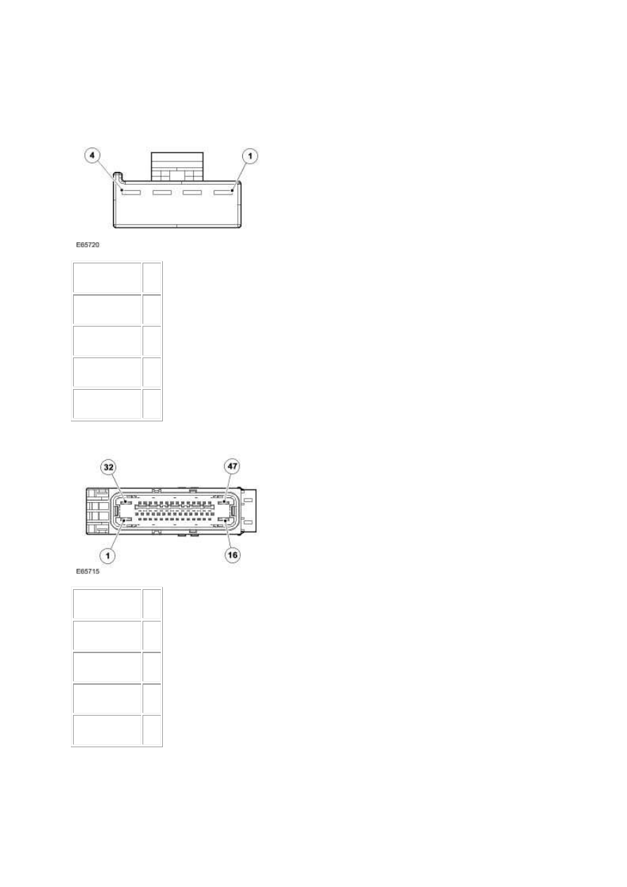
1.
Circuit
Pin
Sensor power 01
Signal B
02
Signal A
03
Sensor return 04
2.
Circuit
Pin
Sensor power 05
Signal B
09
Signal A
41
Sensor return 40
3. Key off. 4. Disconnect the steering wheel rotation sensor connector, IP037. 5. Key on, engine off. 6.
Measure the voltage between:
www.
Нет комментариевНе стесняйтесь поделиться с нами вашим ценным мнением.
Текст