Jaguar XJ (X350). Manual — part 995
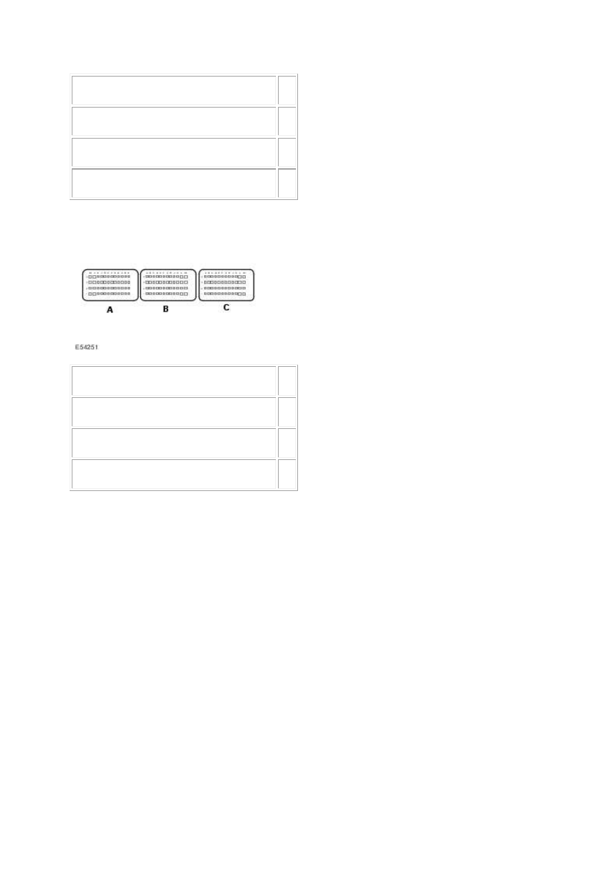
Circuit
Pin
Accelerator pedal position sensor 1 - signal
04
Accelerator pedal position sensor 1 - power 05
Accelerator pedal position sensor 1 - return 03
2.
Circuit
Pin
Accelerator pedal position sensor 1 - signal
D1
Accelerator pedal position sensor 1 - power E1
Accelerator pedal position sensor 1 - return C1
3. Key on, engine off. 4. Make sure the accelerator pedal is released. 5. Access the ECM-Pedal
position sensor 1 (voltage) PID using the Jaguar approved diagnostic system or a scan tool.
Is the voltage between 0 - 1 volts?
-> Yes
GO to Pinpoint Test G549822t85.
-> No
GO to Pinpoint Test G549822t86.
G549822t85 : CHECK THE APP1 VALUE, WITH THE ACCELERATOR FULLY
DEPRESSED
1. Make sure the accelerator pedal is fully depressed. 2. Access the ECM-Pedal position sensor 1
(voltage) PID using the Jaguar approved diagnostic system or a scan tool.

Is the voltage between 2.2 - 2.7 volts?
-> Yes
An intermittent fault may be present in the wiring harness. Visually check for chaffed wires or other
physical damage to the harness.
-> No
GO to Pinpoint Test G549822t86.
G549822t86 : CHECK THE APP1 SENSOR RETURN CIRCUIT FOR HIGH
RESISTANCE
1. Key off. 2. Disconnect the APP sensor connector, CR14. 3. Key on, engine off. 4. Measure the
resistance between:
CR14, harness side
Battery
Pin 03
Negative terminal
Is the resistance less than 10 ohms?
-> Yes
GO to Pinpoint Test G549822t87.
-> No
GO to Pinpoint Test G549822t104.
G549822t87 : CHECK FOR POWER TO THE APP1 SENSOR
1. Measure the voltage between:
CR14, harness side
Battery
Pin 05
Negative terminal
Is the voltage between 4.8 - 5.2 volts?
-> Yes
GO to Pinpoint Test G549822t88.
www.

-> No
GO to Pinpoint Test G549822t96.
G549822t88 : CHECK THE APP1 SIGNAL CIRCUIT FOR SHORT CIRCUIT TO
GROUND
1. Measure the resistance between:
CR14, harness side
Battery
Pin 04
Negative terminal
Is the resistance greater than 100 Kohms?
-> Yes
GO to Pinpoint Test G549822t89.
-> No
GO to Pinpoint Test G549822t92.
G549822t89 : CHECK THE APP1 SIGNAL CIRCUIT FOR SHORT CIRCUIT TO
POWER
1. Measure the resistance between:
CR14, harness side
Battery
Pin 04
Positive terminal
Is the resistance greater than 100 Kohms?
-> Yes
GO to Pinpoint Test G549822t90.
-> No
GO to Pinpoint Test G549822t94.

G549822t90 : CHECK THE APP1 SIGNAL AND POWER CIRCUITS FOR SHORT
CIRCUIT TO EACH OTHER
1. Measure the resistance between:
CR14, harness side CR14, harness side
Pin 04
Pin 05
Is the resistance greater than 100 Kohms?
-> Yes
GO to Pinpoint Test G549822t91.
-> No
GO to Pinpoint Test G549822t95.
G549822t91 : CHECK THE APP1 SIGNAL CIRCUIT FOR HIGH RESISTANCE
1. Key off. 2. Disconnect the ECM connector, EC66. 3. Measure the resistance between:
CR14, harness side EC66, harness side
Pin 04
Pin D1
Is the resistance less than 10 ohms?
-> Yes
An intermittent fault may be present in the wiring harness. Visually check for chaffed wires or other
physical damage to the harness. If no fault is found in the circuit, suspect the following
component(s): - APP connector - APP sensor - ECM connector - ECM
-> No
REPAIR the high resistance circuit. For additional information, refer to the wiring diagrams. Clear any
DTCs, test the system for normal operation.
G549822t92 : CHECK THE APP1 SIGNAL AND RETURN CIRCUITS FOR SHORT
CIRCUIT TO EACH OTHER
1. Key off. 2. Disconnect the ECM connector, EC66. 3. Key on, engine off. 4. Measure the resistance
between:
www.
Нет комментариевНе стесняйтесь поделиться с нами вашим ценным мнением.
Текст