Jaguar XJ (X350). Manual — part 311

Engine ground strap retaining bolt
10
7
-
Engine front cover retaining bolts
A
-
-
Engine mounting bracket retaining bolts
40
30
-
Engine mount bracket to engine mount retaining nuts
55
40
-
Engine mount retaining bolts to crossmember retaining nuts 63
46
-
Engine mount/oil filter housing retaining bolts
A
-
-
Engine wiring harness retaining bracket
7
-
62
Exhaust manifold heat shield retaining bolts
10
7
-
Exhaust manifold retaining studs
9
-
80
Exhaust manifold retaining nuts
A
-
-
Flywheel retaining bolts
80
59
-
Flexplate retaining bolts
80
59
-
Generator retaining bolts
48
35
-
Ignition coils retaining bolts
7
-
62
Knock sensor retaining bolts
25
18
-
Lower cylinder block retaining bolts
A
-
-
Lower intake manifold retaining bolts
A
-
-
Oil level indicator tube retaining bolt
10
7
-
Oil pan retaining bolts
A
-
-
Oil pan drain plug
24
18
-
Oil pressure sensor
16
12
-
Oil pump to engine block retaining bolts
10
7
-
Oil separator blanking plate
10
7
-
Oil temperature sensor
14
10
-
Power steering pump retaining bolts
25
18
-
Spark plugs
15
11
-
Timing chain guide retaining bolts
A
-
-
Timing chain tensioner retaining bolts
25
18
-
Upper intake manifold retaining bolts
A
-
-
Upper intake manifold support retaining bolts
10
7
-
Variable camshaft timing oil control unit retaining bolt
40 + 90° 30 + 90° -
Valve cover studs and retaining bolts
A
-
-
Water pump retaining bolts
25
18
-
Wiring harness to valve cover retaining nuts
10
7
-
A = refer to the procedure for correct torque sequence
-
-
-
General procedures
Valve Clearance Adjustment (12.29.48)
1. Remove the left-hand valve cover.
2. Remove the right-hand valve cover.
Valve Cover RH (12.29.44)
3. Turn the crankshaft pulley clockwise to position the relevent camshaft lobe 180 degrees to
the shim being replaced.
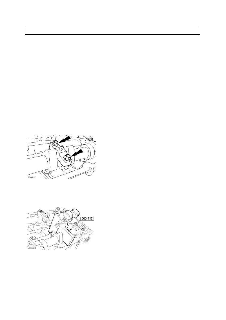
4. Remove the camshaft bearing cap.
5. Install the special tool.
•
Making sure the legs of the tool are in contact with the edge of the valve bucket,
compress the bucket.
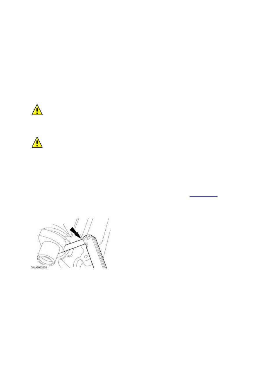
6. Use compressed air to remove the shims that require replacing.
•
Blow compressed air between the shim edge and bucket to dislodge the shim.
7. Use the following formula to calculate the required shim thickness.
•
Original shim thickness + measured clearance - desired clearance = required shim
www.
thickness.
8. Apply a light coat of engine oil to the replacement shim(s) and install.
9. Install the left-hand valve cover.
10. Install the right-hand valve cover.
Valve Cover RH (12.29.44)
Valve Clearance Check (12.29.47)
1. Remove the left-hand valve cover. For additional information, refer to .
2. Remove the right-hand valve cover. For additional information, refer to .
3.
CAUTION: Rotating the crankshaft in a counterclockwise direction may cause
engine damage. Crankshaft journals are directionally machined. Rotating the
crankshaft counterclockwise Can raise burrs on bearing surfaces, reducing engine life.
CAUTION: Camshaft lobes must be 180 degrees away from each valve tappet or
valve clearance will be incorrect.
Rotate the engine clockwise to position the camshaft lobe away from the shim surface.
4. Using the feeler gauge set, measure the clearance between the camshaft and the shim
surface. Record and check the readings. For additional information, refer to <<303-00>>.
Adjust the clearances as necessary. For additional information, refer to.
5. Install the right-hand valve cover. For additional information, refer to .
6. Install the left-hand valve cover. For additional information, refer to .
www.
Нет комментариевНе стесняйтесь поделиться с нами вашим ценным мнением.
Текст