Jaguar XJ (X350). Manual — part 371
All moving parts are lubricated either by pressure or splash oil. Pressurized oil is also provided for
operation of the variable valve timing units and the timing gear chain tensioners.
All of the oil system components are installed on the structural sump.
Oil is returned to the oil pan under gravity through large drain holes in the cylinder heads and the
engine block to make sure quick return of the oil.
Oil Pick-Up
The plastic moulded oil pick-up is attached to the underside of the structural sump. It is immersed in
the oil reservoir to provide a supply to the oil pump during all normal vehicle attitudes. A castellated
inlet allows the supply to be maintained after any deformation of the sump pan (e.g. after
grounding). A mesh screen in the inlet prevents debris from entering the oil system.
Oil Pressure Switch
Installed at the right front of the structural sump, the oil pressure switch connects a ground input to
the instrument cluster when oil pressure is present. This switch operates at a pressure of 0,15 to 0,41
bar (2.2 to 5.9 lbf.in2).
Oil Pump
The oil pump is fitted at the front of the engine and is driven directly by the crankshaft. The inlet and
outlet ports align with oil passages in the bedplate, with a rubber coated metal gasket to seal the
pump to bedplate interface.
An integral pressure relief valve regulates pump outlet pressure at 4,5 bar (65.25lbf.in2).
Oil Pan
The oil pan/sump comprises an aluminium-alloy structural sump bolted to the bedplate and a
pressed steel pan with integral sump plug, bolted to the structural sump.
Oil Filler Cap
The oil filler cap is located on the top of the left-hand bank valve cover.
Windage Tray
A windage tray attached to the top of the structural sump isolates the oil pan from the disturbed air
flow, caused by the rotation of the crankshaft; preventing oil aeration and improving oil drainage.
Crankcase Ventilation
The engine is ventilated through a part-load and a full-load breather; one on each valve cover. These
flexible plastic hoses incorporate O-ring seals and quick release connectors.
The part-load breather ventilates the left-hand valve cover (B-bank) and feeds onto the throttle body
adaptor and the purge valve. This breather is connected between the oil separator in the cover and
the induction elbow.
The full-load breather ventilates the right-hand cover (A-bank) and is connected between the oil
separator in the cover and the air intake duct between the mass air flow (MAF) sensor and the
throttle body.
The MAF sensor unit combines the two sensors: one for air flow and one for air inlet temperature. It
is a hot wire sensor that provides an input which is (approximately) proportional to the mass air flow
into the engine.
Each valve cover oil separator consists of wire gauze packed into an open ended enclosure in the top
of the cover, below the breather outlet.
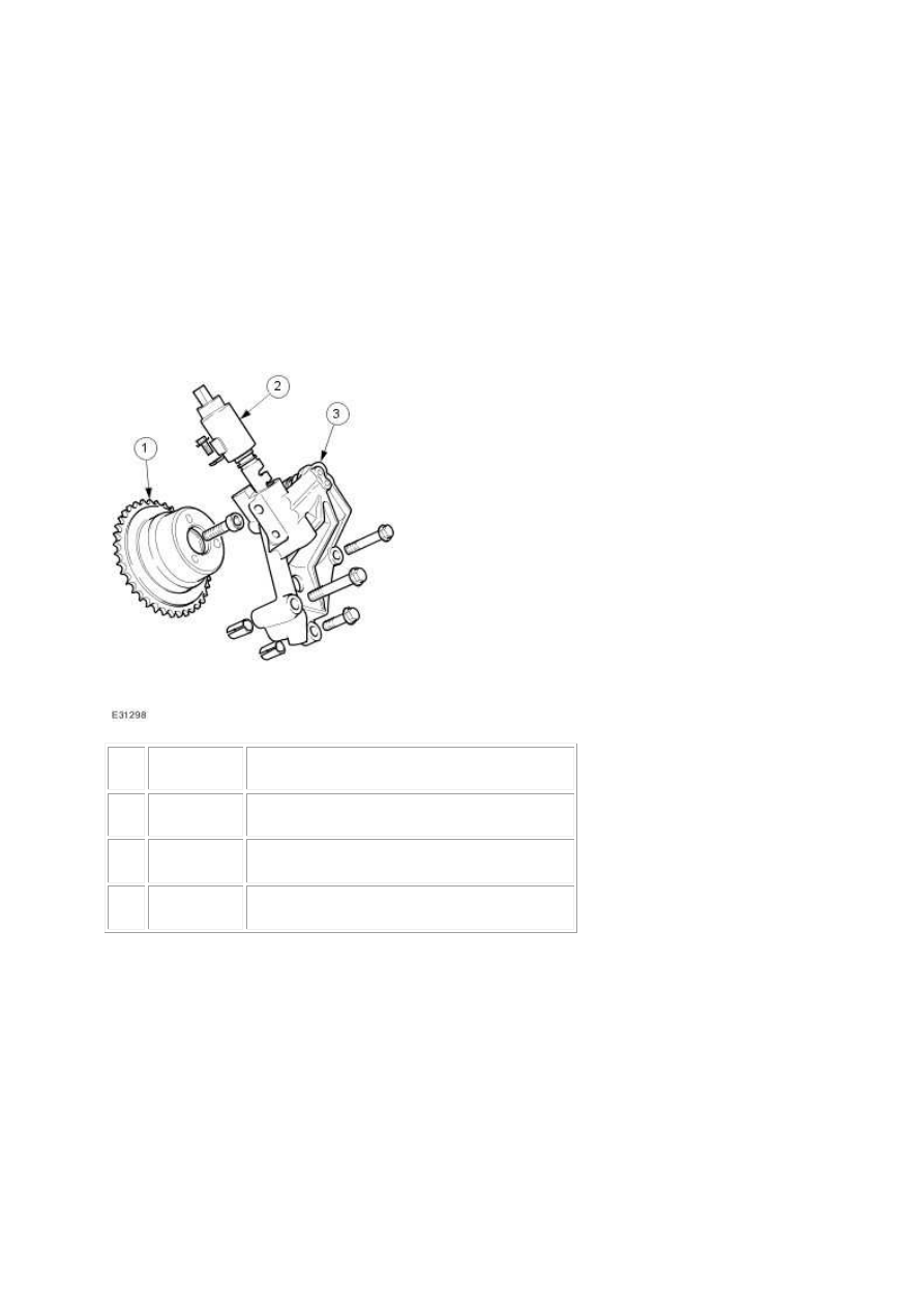
Variable Valve Timing (VVT)
Item
Part Number
Description
1
—
Variable valve timing (VCT) oil control unit
2
—
Variable valve timing (VCT) oil control solenoid
3
—
Bush carrier
The variable valve timing system improves both low speed and high speed engine performance,
engine idle quality and exhaust emissions. It is an infinitely variable system operating on the intake
camshafts only. There is the equivalent of 48º of crankshaft movement between the retarded and
advanced positions. Engine oil pressure operates the system under the control of the ECM.
www.
Removal and installation
Crankshaft Main Bearing Carrier
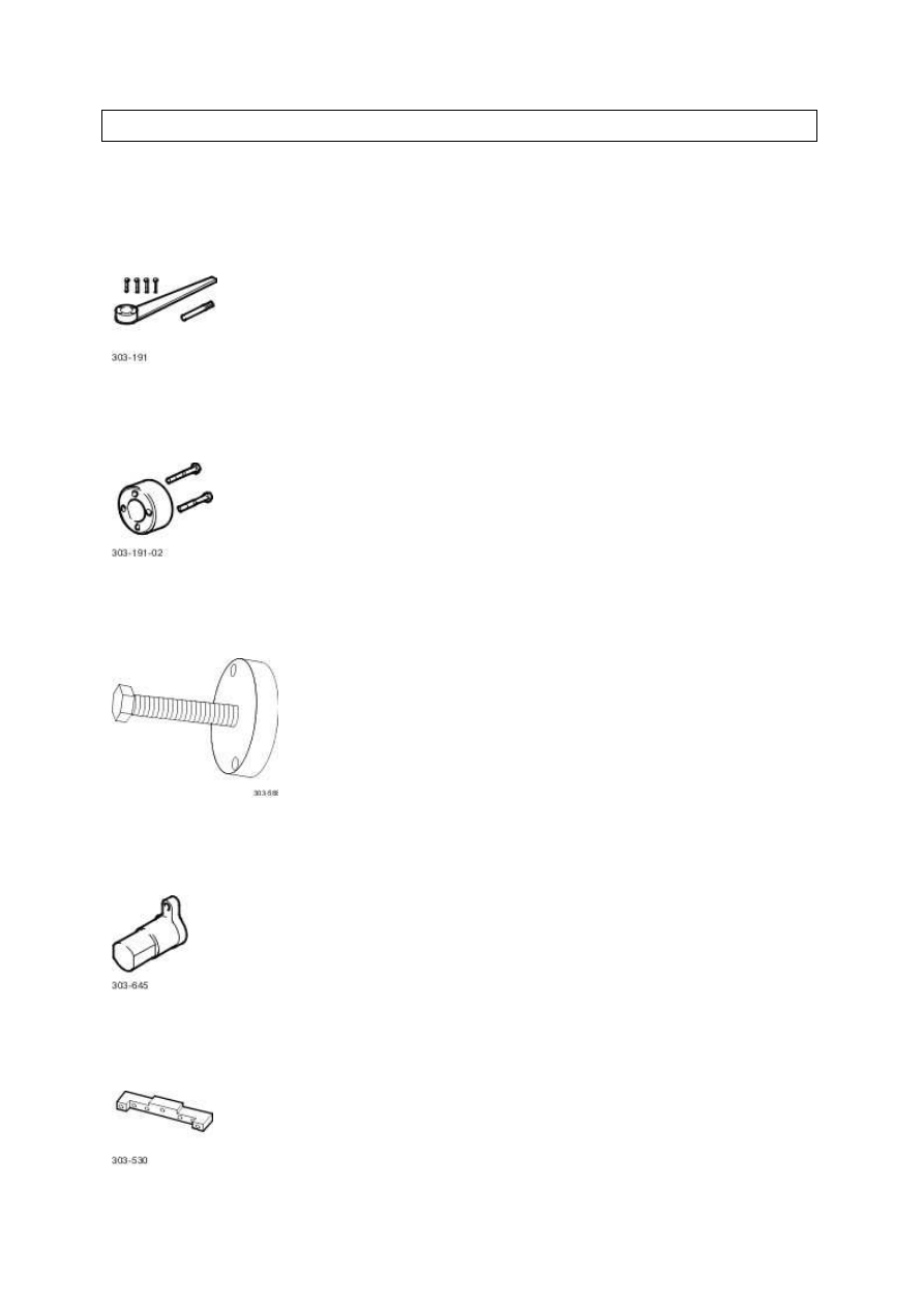
Special Service Tools
Crankshaft locking, main tool
303-191
Adapter
303-191-02
Crankshaft pulley/damper remover
303-588
Crankshaft setting, main tool
303-645
www.
Нет комментариевНе стесняйтесь поделиться с нами вашим ценным мнением.
Текст