Jaguar XJ (X350). Manual — part 369
Valve Clearance Check (12.29.47)
1. Remove the left-hand valve cover.
2. Remove the right-hand valve cover.
3.
CAUTION: Rotating the crankshaft in a counterclockwise direction may cause
engine damage. Crankshaft journals are directionally machined. Rotating the
crankshaft counterclockwise can raise burrs on bearing surfaces, reducing engine life.
CAUTION: Camshaft lobes must be 180 degrees away from each valve tappet or
the valve clearance will be incorrect.
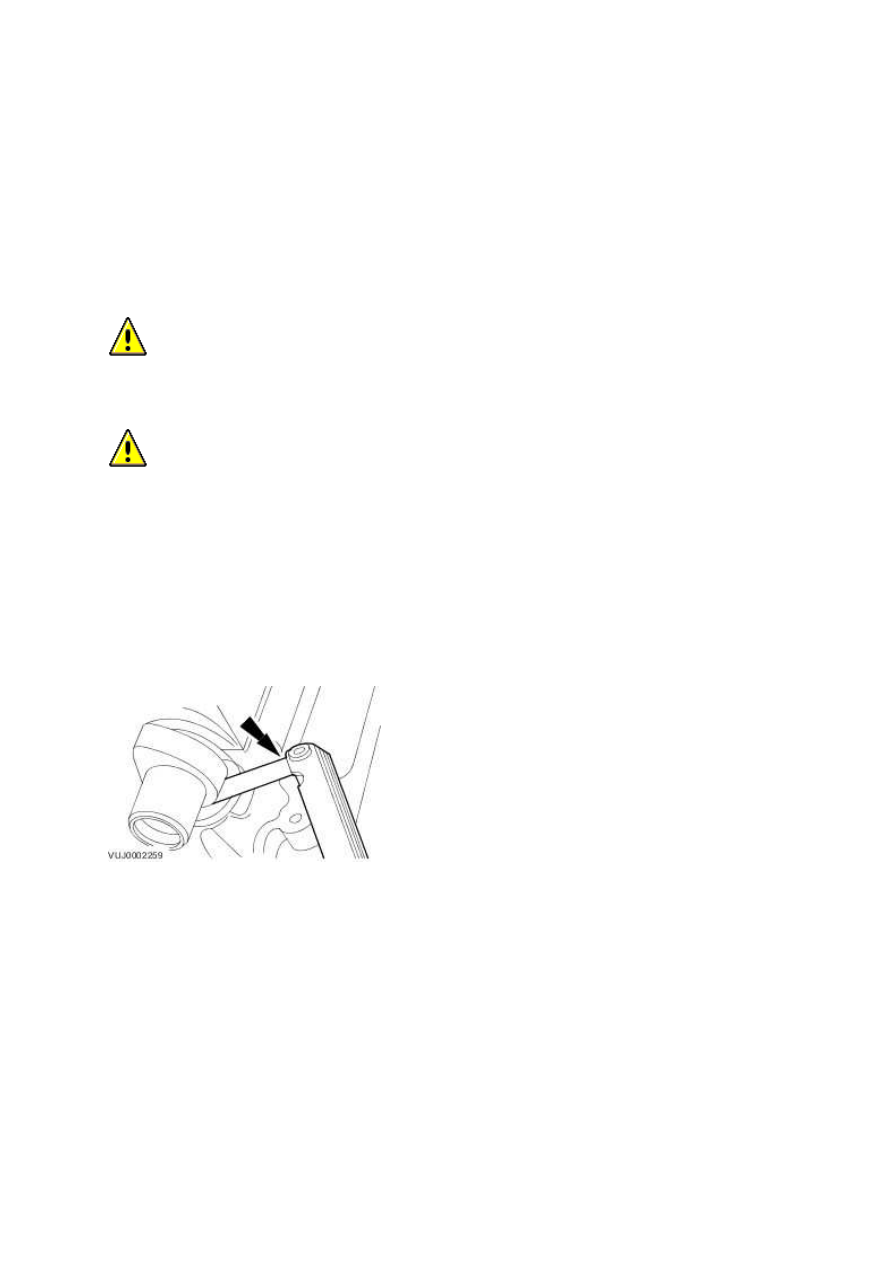
Rotate the engine clockwise to position the camshaft lobe away from the shim surface.
4. Using the feeler gauge set, measure the clearance between the camshaft and the shim
surface. Record and check the readings. Adjust the clearances as necessary.
Valve Clearance Check (12.29.47)
5. Install the right-hand valve cover.
6. Install the left-hand valve cover.
Description and operation
Engine
Cylinder Block
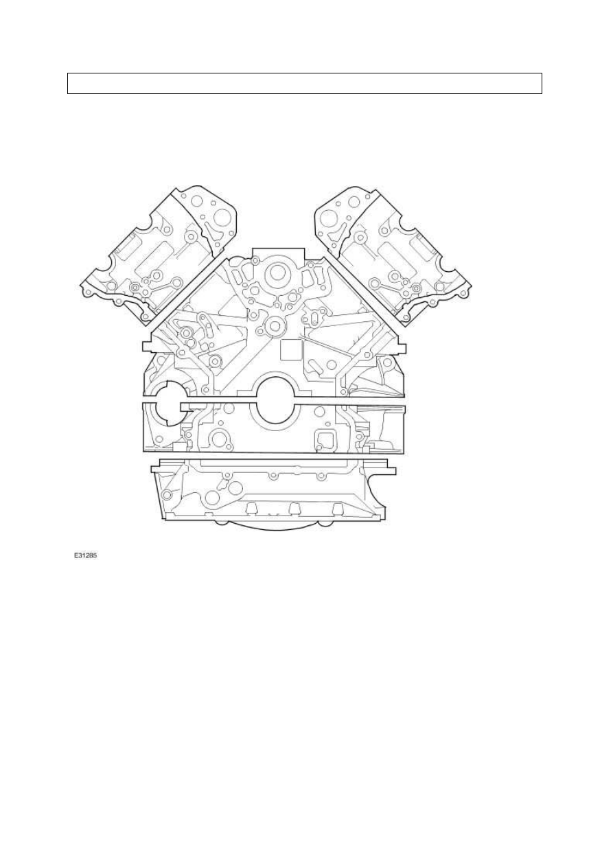
The 3.5L & 4.2L engine consists of an eight cylinder 90 degree 'Enclosed V' configuration liquid cooled
aluminium cylinder block with dry cast liners.
Viewed from the driving position, the right-hand cylinder bank is designated A-bank and the left-
hand cylinder bank as B-bank.
Cylinder Block Drain Plug
The coolant drain plug is located on the rear left side of the cylinder block.
On vehicles supplied with a cold climate package (i.e. vehicles operating in conditions regularly below
-30ºC) a cylinder block heater unit is fitted instead of the drain plug.
www.
Knock Sensors
Two knock sensors are fitted to the cylinder block on the inboard side of each cylinder bank. The
electrical connector of each sensor is secured to the left-hand engine cover bracket.
These piezo-electric sensors provide inputs to the engine control module (ECM) to indicate the
detection and location of detonation during combustion.
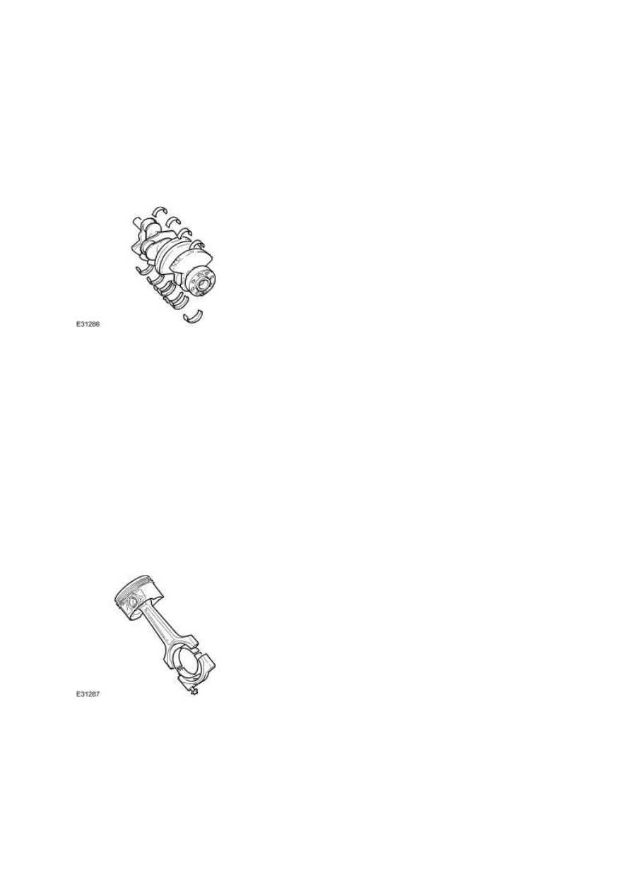
Crankshaft
The cast iron crankshaft has undercut and rolled fillets for improved strength and six counter-balance
weights make sure low levels of vibration from the four throw, five bearing configuration.
The main bearing shells are aluminium/tin split plain type. An oil groove in the top half of each
bearing transfers oil into the crankshaft oilway drillings for lubrication of the connecting rod
bearings. A lead/bronze thrust washer is fitted on each side of the top half of the center main
bearing.
The crankshaft rear oil seal is lipped and is a press fit in the interface of the bedplate to cylinder
block.
A torsional vibration crankshaft damper pulley is bolted to the front of the crankshaft.
Connecting Rods and Pistons
The connecting rods are manufactured from sinter-forged steel and have fracture-split bearing caps.
The opposing sides of each connecting rod being fractured at the bearing horizontal center line.
The cylinder position is etched on adjoining sides of the joint to identify matching connecting rods
and bearing caps. The connecting rod bearing shells are lead/bronze, split plain bearings.
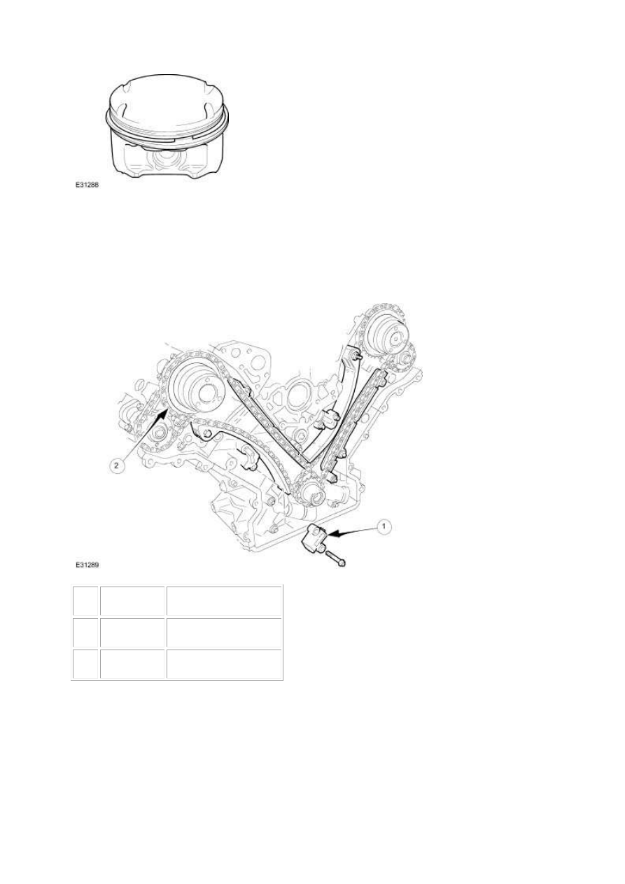
The pistons are open ended skirt design with small recesses for valve clearance and flat upper
surfaces to reduce heat absorption. Three piston rings, two compression and one oil control, are
fitted to each piston. Each piston is fitted on a gudgeon pin which is in a lead/bronze bush fitted in
the connecting rod.
Timing Gear
Item
Part Number
Description
1
—
Primary chain tensioner
2
—
Primary chain
Multi link primary and single link secondary chains drive the camshafts of each cylinder bank. The
primary chains transmit the drive from sprocket on the crankshaft to a sprocket on each intake
camshaft. The secondary chains transmit the drive from a second, smaller sprocket on the intake
camshaft to a sprocket on the exhaust camshaft.
Each chain has a hydraulic tensioner operated by the engine lubricating system. A jet of oil from the
end of each tensioner lubricates the chains. The primary chain tensioners act on pivoting flexible
www.
Нет комментариевНе стесняйтесь поделиться с нами вашим ценным мнением.
Текст