Jaguar XJ (X350). Manual — part 46
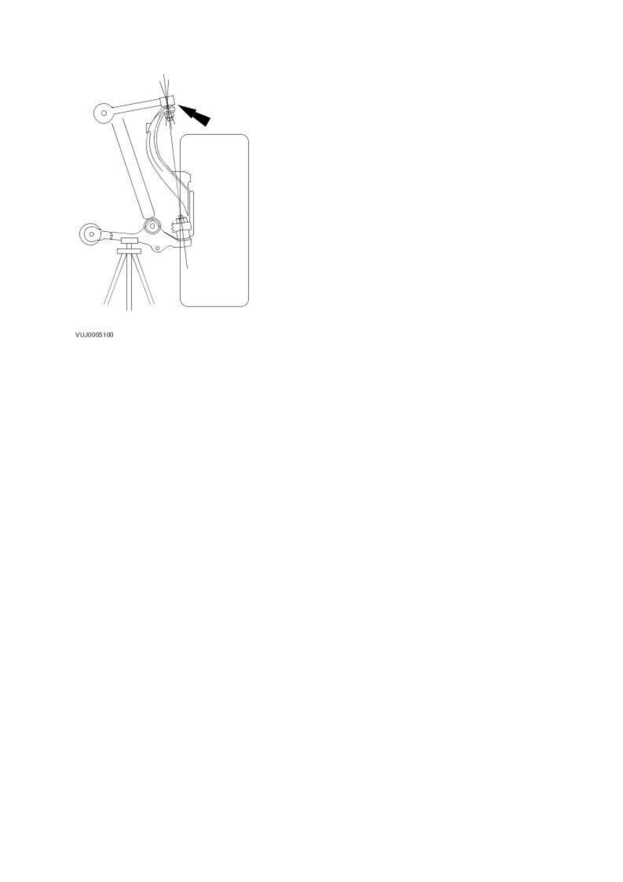
4 . While an assistant pulls and pushes the top and bottom of the tire, observe the relative
movement between the ball joint and the front suspension lower arm. Any movement at or
exceeding the specification indicates a worn or damaged ball joint. Install a new wheel knuckle as
necessary.
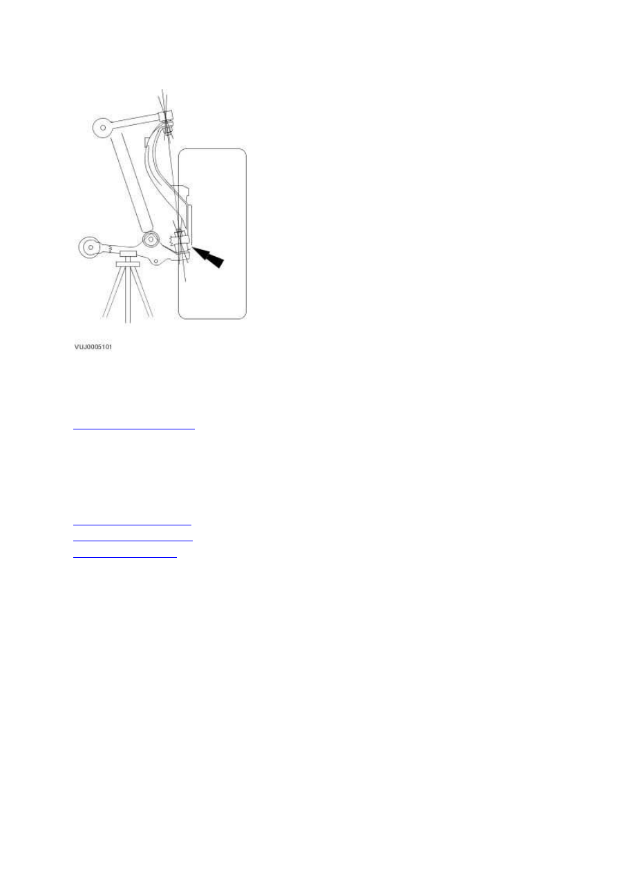
Wheel Knuckle (60.25.23)
5 . While an assistant pulls and pushes the top and bottom of the tire, observe the relative
movement between the ball joint and the front suspension upper arm or rear suspension upper arm.
Any movement at or exceeding the specification indicates a worn or damaged ball joint. Install a new
upper arm as necessary. Refer to
Upper Arm LH (60.35.41)
Upper Arm RH (60.35.42)
or
Upper Arm (64.25.31)
.
7 . Lower the vehicle.
6 . Remove the safety stand.
www.
204-01 : Front Suspension
Specification
Specifications
Torque Specifications
Description
Nm lb-ft lb-in
Rear lower arm ball joint retaining nut
Torque Specifications – Armoured XJ
ly upper retaining nuts 25 18
-
75 55 -
Shock absorber and spring assemb
Description
Nm lb-ft lb-in
Steering gear to subframe retaining bolts
100 74 -
Stabilizer bar link retaining nut
43 32 -
Stabilizer bar link retaining nut and bolt
70 52 -
Stabilizer bar clamp retaining bolts
55 41 -
Rear lower arm ball joint retaining nut
92 68 -
Front and rear lower arm to subframe retaining nut and bolt 175 129 -
Front lower arm to rear lower arm retaining nut and bolt
A A
A
Upper arm ball joint retaining nut
90 66 -
Upper arm to body retaining nuts and bolts
47 35 -
Air spring assembly to lower arm retaining bolt
175 129 -
Tie-rod end to wheel knuckle retaining nut
75 55 -
Wheel hub and bearing to wheel knuckle retaining bolts
90 66 -
Exhaust manifold to cylinder head retaining nuts (3.0l only) 20 15 -
Dipstick tube retaining bolt
10 7
-
Engine mount lower retaining nut
55 41 -
Front subframe front retaining bolt
200 148 -
Front subframe rear retaining bolt
115 85 -
Wheel and tire retaining nuts
125 92 -
Hydraulic control unit retaining bolts
9
-
80
A = refer to the procedure for the correct torque sequence -
-
-
Description and operation
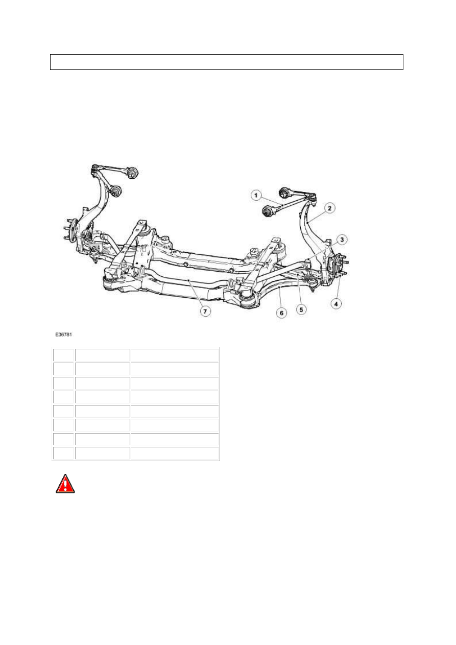
Front Suspension
Item Part Number
Description
1
—
Upper arm
2
—
Wheel knuckle
3
—
Stabilizer bar link
4
—
Wheel bearing and hub
5
—
Rear lower arm
6
—
Front lower arm
7
—
Stabilizer bar
WARNING: No attempt must be made to weld or repair the front subframe. If it
is damaged a new one must be installed. Failure to follow this instruction may result in
personal injury.
The independent front suspension is of the double wishbone type and is mounted on the front
subframe, the front subframe consisting of a pressed steel fabrication.
The rear of the front subframe provides the mounting points for the power assisted steering
gear and the engine mounts.
www.
Нет комментариевНе стесняйтесь поделиться с нами вашим ценным мнением.
Текст