Jaguar XJ (X350). Manual — part 237

6
—
Wheel speed sensor - front
7
—
Brake pedal switch
8
—
Anti-lock brake system (ABS)/Dynamic stability control hydraulic control
modulator (HCU)
The ABS modulates brake pressure on each wheel independently to maintain vehicle stability during
braking. The ABS continually monitors the rotational velocity of each wheel during driving and
determines if a tire is skidding when the brakes are applied. Only then does the ABS intervene to
modulate the brake pressure to the skidding wheel. The modulation continues until the wheel
rotates freely. The brake pressure is then restored and the modulate/restore cycle is repeated
whenever skidding is detected. This cycle occurs at a rate of several times per second.
The ABS/dynamic stability control module is capable of detecting the following system conditions:
•
hydraulic valve failure
•
wheel speed sensor failure
•
ABS power relay short circuit
•
interconnect failures to the ABS sensors, power and ground to the ABS module
•
over/under voltage conditions.
The ABS provides self-diagnostics and displays failure messages through the ABS warning indicator in
the instrument cluster. Failure of the ABS module, for whatever reason, will not compromise the
normal operation of the brake system.
The dynamic stability control system includes the:
•
anti-lock brake system
•
lateral/yaw control
•
full speed traction control.
The dynamic stability control system manages the braking system to enhance the driver control of
the vehicle.
The dynamic stability control system continually monitors the steering wheel angle, master cylinder
brake pressure, front and rear wheel speeds and vehicle lateral/yaw rate acceleration.
The dynamic stability control module supports speed control and stability assist functions.
The lateral/yaw rate sensor supplies a signal to the dynamic stability control module, via a serial link,
which monitors the vehicles rate of acceleration from its central axis in a sideways direction, and also
the vehicles angular rotation around it's central axis.
The driver input parameters are continually monitored by the steering wheel rotation sensor and the
HCU master cylinder pressure sensor.
Dynamic stability control is enabled/disabled through the traction control ON/OFF switch.
Self-diagnosis of the dynamic stability control system is provided through the instrument cluster and
message center.
Traction control is an additional function added to the ABS/dynamic stability control system. The
vehicles driven wheels are continually monitored for wheel spin relative to the calculated reference
speed and to each other. If wheel spin is detected, the traction control function intervenes
independently of the driver, applying brake pressure to the spinning wheel and reducing the engine
drive torque supply. Meanwhile, brake pressure is modulated by the traction control until traction is
re-established. Traction control brake actuation is diminished above 40 kph (25 mile/h). Above this
speed, traction control relies primarily on engine torque reduction.
Traction control is enabled/disabled through the traction control ON/OFF switch. When the switch is
in the OFF position, the amber traction control warning lamp solidly illuminates within the
instrument cluster message center. The traction control is automatically activated when the ignition
is switched on. Self-diagnosis of the traction control system is also provided through the instrument
cluster and message center.
The traction control brake intervention is automatically disabled whenever the brakes exceed a
temperature limit. The traction brake intervention will remain disabled until the brakes have cooled.
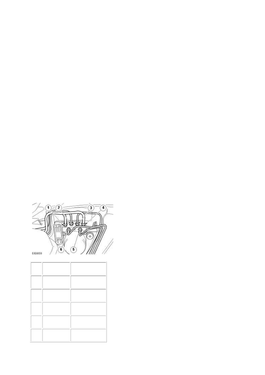
Hydraulic Control Modulator Brake Tube Location - Left-hand Drive
Item
Part Number
Description
1
—
Secondary circuit
2
—
Front left-hand
3
—
Front right-hand
4
—
Primary circuit
5
—
Rear left-hand
www.

6
—
Rear right-hand
Hydraulic control Modulator Brake Tube Location - Right-hand Drive
Item
Part Number
Description
1
—
Secondary circuit
2
—
Front left-hand
3
—
Front right-hand
4
—
Primary circuit
5
—
Rear left-hand
6
—
Rear right-hand
Brake Vacuum Assist (3.0L V6 and 3.5L V8 Vehicles Only)
Operation of Brake Vacuum Assist is possible at the start of an ignition cycle when the engine is cold
and low vacuum levels are generated by the engine. Its operation will result in vibrating pedal and
some modulator noise. This may appear to be similar to unexpected ABS (anti-lock brake system)
function, at lower than expected speed or light braking effort. As the engine warms up, Brake
Vacuum Assist operation should become less frequent, though it can be active in other circumstances
where vacuum levels are lower than required; for example, at higher altitudes or during frequent,
heavy braking.
Additionally, noise levels during Brake Vacuum Assist may be variable, with initial system activity
louder than normal activity. In some circumstances initial activity louder than normal may be
interpreted as a 'thump' noise, particularly if there is no significant Brake Vacuum Assist functionality
that immediately follows.
In these cases, this system behaviour is not unexpected, and should not be a cause for fault
investigation.
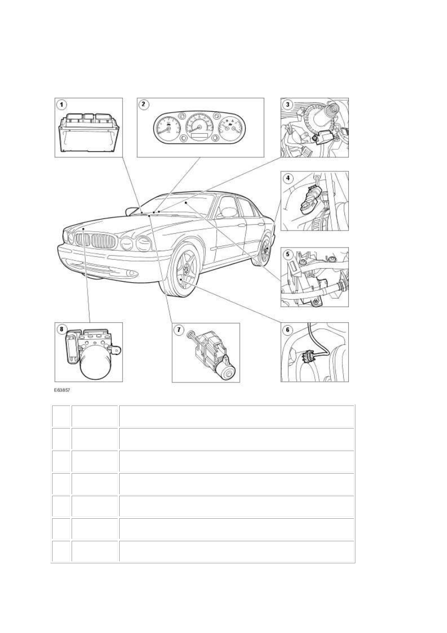
Anti-Lock Control - Stability Assist
COMPONENT LOCATION
Item
Part Number
Description
1
Engine Control Module (ECM)
2
Instrument cluster and message centre
3
Steering angle sensor
4
Wheel speed sensor - rear
5
Lateral/yaw rate sensor
6
Wheel speed sensor - front
www.
Нет комментариевНе стесняйтесь поделиться с нами вашим ценным мнением.
Текст