Jaguar XJ (X350). Manual — part 1022

G549822t266 : CHECK THE RADIATOR COOLING FAN MODULE CONTROL
CIRCUIT FOR SHORT CIRCUIT TO GROUND
1. Measure the resistance between:
GC01, harness side
Battery
Pin 01
Negative terminal
Is the resistance greater than 100 Kohms?
-> Yes
GO to Pinpoint Test G549822t267.
-> No
REPAIR the short circuit. For additional information, refer to the wiring diagrams. Clear any DTCs, test
the system for normal operation.
G549822t267 : CHECK THE RADIATOR COOLING FAN MODULE CONTROL
CIRCUIT FOR SHORT CIRCUIT TO POWER
1. Measure the resistance between:
GC01, harness side
Battery
Pin 01
Positive terminal
Is the resistance greater than 100 Kohms?
-> Yes
GO to Pinpoint Test G549822t268.
-> No
REPAIR the short circuit. For additional information, refer to the wiring diagrams. Clear any DTCs, test
the system for normal operation.
G549822t268 : CHECK THE RADIATOR COOLING FAN MODULE CONTROL
CIRCUIT FOR HIGH RESISTANCE
1. Key off. 2. Disconnect the ECM connector, EC66. 3. Key on, engine off. 4. Measure the resistance
between:

GC01, harness side EC66, harness side
Pin 01
Pin K2
Is the resistance less than 10 ohms?
-> Yes
An intermittent fault may be present in the wiring harness. Visually check for chaffed wires or other
physical damage to the harness. If no fault is found in the circuit, suspect the following
component(s): - Radiator cooling fan module connector(s) - Radiator cooling fan module - ECM
connector - ECM
-> No
REPAIR the high resistance circuit. For additional information, refer to the wiring diagrams. Clear any
DTCs, test the system for normal operation.
PINPOINT TEST G549822p22 :
STARTER RELAY AND CIRCUITS
G549822t261 : CHECK THE STARTER RELAY AND CIRCUITS
1.
Starting System
-> Yes
-> No
PINPOINT TEST G549822p23 : ECM
POWER SUPPLY CIRCUIT
www.
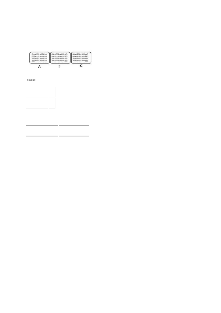
G549822t269 : CHECK FOR POWER TO THE ECM
1.
Circuit
Pin
ECM - power K4
2. Key off. 3. Disconnect the ECM electrical connector, EC66. 4. Measure the voltage between:
EC66, harness side
Battery
Pin K4
Negative terminal
Is the voltage greater than 10 volts?
-> Yes
Recheck the DTCs. If no DTCs are set an intermittent fault may be present in the wiring harness.
Visually check for chaffed wires or other physical damage to the harness. If no fault is found in the
circuit, suspect the following component(s): - ECM connector - ECM
-> No
REPAIR the power supply circuit as necessary. For additional information, refer to the wiring
diagrams. Clear any DTCs, test the system for normal operation.
PINPOINT TEST G549822p20 : ECM
IGNITION SUPPLY CIRCUIT(S)
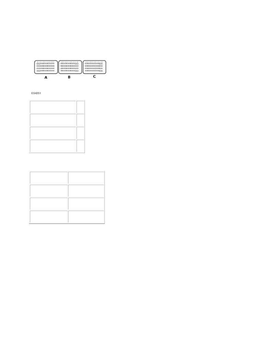
G549822t257 : CHECK THE IGNITION TO ECM SUPPLY CIRCUITS
1.
Circuit
Pin
ECM - ignition supply A L2
ECM - ignition supply B L3
ECM - ignition supply C L1
2. Key off. 3. Disconnect the ECM electrical connector, EC66. 4. Measure the voltage between:
EC66, harness side
Battery
Pin L2
Negative terminal
Pin L3
Negative terminal
Pin L1
Negative terminal
Are the voltages greater than 10 volts?
-> Yes
Recheck the DTCs. If no DTCs are set an intermittent fault may be present in the wiring harness.
Visually check for chaffed wires or other physical damage to the harness. If no fault is found in the
circuit, suspect the following component(s): - ECM connector - ECM
-> No
REPAIR the ignition power supply circuit(s) as necessary. For additional information, refer to the
wiring diagrams. Clear any DTCs, test the system for normal operation.
PINPOINT TEST G549822p26 : EMS
CONTROL RELAY
www.
Нет комментариевНе стесняйтесь поделиться с нами вашим ценным мнением.
Текст