Jaguar XJ (X350). Manual — part 754

303-07B : Engine Ignition – 4.2L NA V8 – AJV8/4.2L SC
V8 – AJV8/3.5L NA V8 – AJV8
Specifications
Specifications
General Specifications
Item
Specification
Firing order
1-5-4-2-6-3-7-8
Spark plug type - Vehicles with supercharger
NGK-IFR-5N10
Spark plug type - Vehicles without supercharger NGK-IFR-5N10
Torque Specifications
Description
Nm lb-ft lb-in
Spark plugs
27 18 -
Ignition coil-on-plug retaining bolts 5
-
44
Description and operation
Engine Ignition
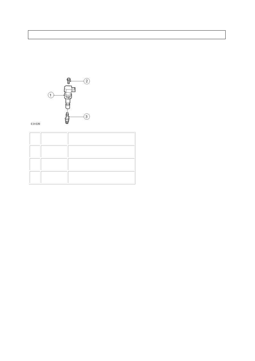
Component Locations
Item
Part Number
Description
1
-
Ignition coil-on-plug
2
-
Ignition coil-on-plug retaining bolt
3
-
Spark plug
The right-hand cylinders are numbered 7, 5, 3, 1 and the left-hand cylinders are numbered 8, 6, 4, 2
when viewed from the rear of the engine.
An ignition coil is located on each individual spark plug allowing the ignition timing to be adjusted
independently.
The crankshaft position (CKP) sensor signal is the basis for ignition timing calculations. The
alternating voltage signal from the CKP sensor is converted to a digital signal by the engine control
module (ECM). This digital signal is then used to position the closing time of the primary circuit of the
ignition coil. The effective range for ignition timing control is increased to the fact that there are no
rotating parts.
On the basis of engine speed and load inputs, the ECM determines the ignition timing. This function
also takes other inputs into consideration such as engine temperature, throttle position, knock
control, camshaft position, traction control and electronic transmission control inputs.
This ignition system enables the customer to drive the vehicle home if an ignition coil or ignition coil
wiring failure occurs. In the event of a wiring failure between the ECM and the ignition coil, the
ignition coil will fail instead of the ignition coil fuse blowing, which will allow the remaining ignition
coils to continue to function and the engine to limp home.
www.

Diagnosis and testing
Engine Ignition - VIN Range: G00442-
>G45703
Inspection and Verification
1 . Verify the customer concern.
2 . Confirm which, if any, warning lights and/or messages were displayed on the instrument cluster.
NOTE:
If any warning lights and/or messages were displayed when the fault occurred, refer to the
Driver Information table for DTCs associated with the display, then to the DTC index table for
possible sources and actions. Some warnings will appear to clear when the ignition is cycled. This
is often because the warning has flagged as a result of one of the vehicle's on-board diagnostic
routines having run to detect the fault. If the same routine is not run when the ignition is
switched ON, the warning will not reflag until the routine does run. See the DTC summaries for
drive cycle routines.
3 . Visually inspect for obvious signs of mechanical or electrical damage.
Visual Inspection Chart
Mechanical
Electrical
Engine oil level
Cooling system coolant level
Fuel level
Fuel contamination/grade/quality
Throttle body
Poly-vee belt
Fuses
Wiring harness
Electrical connector(s)
Sensor(s)
Engine control module (ECM)
Transmission control module
1 . Verify the following systems are working correctly:
Air intake system
Cooling system

Charging system
Fuel system
2 . If an obvious cause for an observed or reported concern is found, correct the cause (if possible)
before proceeding to the next step.
3 . Where the Jaguar approved diagnostic system is available, complete the S93 report before
clearing any or all fault codes from the vehicle.
NOTE:
If a DTC cannot be cleared, then there is a permanent fault present that flags again as soon as it
is cleared. (The exception to this is P1260, which will only clear following an ignition OFF/ON
cycle after rectification).
4 . If the cause is not visually evident and the Jaguar approved diagnostic system is not available, use
a fault code reader to retrieve the fault codes before proceeding to the Diagnostic Trouble Code
(DTC) Index Chart, or the Symptom Chart if no DTCs are set.
5 . Using the Jaguar approved diagnostic system where available, and a scan tool where not, check
the freeze frame data for information on the conditions applicable when the fault was flagged. The
format of this will vary, depending on the tool used, but can provide information useful to the
technician in diagnosing the fault.
CAUTION: When probing connectors to take measurements in the course of the pinpoint
tests, use the adaptor kit, part number 3548-1358-00.
NOTE:
When performing electrical voltage or resistance tests, always use a digital multimeter (DMM)
accurate to 3 decimal places, and with an up-to-date calibration certificate. When testing
resistance, always take the resistance of the DMM leads into account.
NOTE:
Check and rectify basic faults before beginning diagnostic routines involving pinpoint tests.
Symptom
Possible source
Action
Engine cranks, but does
Engine breather system
disconnected/restricte
Check engine breather system, <<303-08>>
www.
Нет комментариевНе стесняйтесь поделиться с нами вашим ценным мнением.
Текст