Jaguar XJ (X350). Manual — part 1015
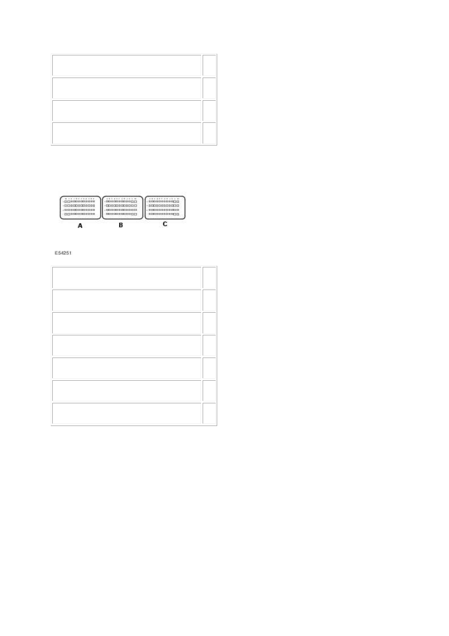
Accelerator pedal position sensor 2 - return 06
Accelerator pedal position sensor 1 - signal
04
Accelerator pedal position sensor 1 - power 05
Accelerator pedal position sensor 1 - return 03
2.
Circuit
Pin
Accelerator pedal position sensor 2 - signal
C2
Accelerator pedal position sensor 2 - power D2
Accelerator pedal position sensor 2 - return B2
Accelerator pedal position sensor 1 - signal
D1
Accelerator pedal position sensor 1 - power E1
Accelerator pedal position sensor 1 - return C1
3. Key on, engine off. 4. Make sure the accelerator pedal is released. 5. Access the ECM-Pedal
position sensor 1 (voltage) PID using the Jaguar approved diagnostic system or a scan tool.
Is the voltage between 0 - 1 volts?
-> Yes
GO to Pinpoint Test G549822t199.
-> No
GO to Pinpoint Test G549822t202.
G549822t199 : CHECK THE APP2 VALUE, WITH THE ACCELERATOR PEDAL
RELEASED
1. Make sure the accelerator pedal is released. 2. Access the ECM-Pedal position sensor 2 (voltage)
PID using the Jaguar approved diagnostic system or a scan tool.
Is the voltage between 3 - 5 volts?
-> Yes
GO to Pinpoint Test G549822t200.
-> No
GO to Pinpoint Test G549822t222.
G549822t200 : CHECK THE APP1 VALUE, WITH THE ACCELERATOR FULLY
DEPRESSED
1. Make sure the accelerator pedal is fully depressed. 2. Access the ECM-Pedal position sensor 1
(voltage) PID using the Jaguar approved diagnostic system or a scan tool.
Is the voltage between 2.2 - 2.7 volts?
-> Yes
GO to Pinpoint Test G549822t201.
-> No
GO to Pinpoint Test G549822t202.
G549822t201 : CHECK THE APP2 VALUE, WITH THE ACCELERATOR FULLY
DEPRESSED
1. Make sure the accelerator pedal is fully depressed. 2. Access the ECM-Pedal position sensor 2
(voltage) PID using the Jaguar approved diagnostic system or a scan tool.
Is the voltage between 2.2 - 2.7 volts?
-> Yes
An intermittent fault may be present in the wiring harness. Visually check for chaffed wires or other
physical damage to the harness.
-> No
GO to Pinpoint Test G549822t222.
www.

G549822t202 : CHECK THE APP1 SENSOR RETURN CIRCUIT FOR HIGH
RESISTANCE
1. Key off. 2. Disconnect the APP sensor connector, CR14. 3. Key on, engine off. 4. Measure the
resistance between:
CR14, harness side
Battery
Pin 03
Negative terminal
Is the resistance less than 10 ohms?
-> Yes
GO to Pinpoint Test G549822t203.
-> No
GO to Pinpoint Test G549822t220.
G549822t203 : CHECK FOR POWER TO THE APP1 SENSOR
1. Measure the voltage between:
CR14, harness side
Battery
Pin 05
Negative terminal
Is the voltage between 4.8 - 5.2 volts?
-> Yes
GO to Pinpoint Test G549822t204.
-> No
GO to Pinpoint Test G549822t212.
G549822t204 : CHECK THE APP1 SIGNAL CIRCUIT FOR SHORT CIRCUIT TO
GROUND
1. Measure the resistance between:
CR14, harness side
Battery

Pin 04
Negative terminal
Is the resistance greater than 100 Kohms?
-> Yes
GO to Pinpoint Test G549822t205.
-> No
GO to Pinpoint Test G549822t208.
G549822t205 : CHECK THE APP1 SIGNAL CIRCUIT FOR SHORT CIRCUIT TO
POWER
1. Measure the resistance between:
CR14, harness side
Battery
Pin 04
Positive terminal
Is the resistance greater than 100 Kohms?
-> Yes
GO to Pinpoint Test G549822t206.
-> No
GO to Pinpoint Test G549822t210.
G549822t206 : CHECK THE APP1 SIGNAL AND POWER CIRCUITS FOR SHORT
CIRCUIT TO EACH OTHER
1. Measure the resistance between:
CR14, harness side CR14, harness side
Pin 04
Pin 05
Is the resistance greater than 100 Kohms?
www.
Нет комментариевНе стесняйтесь поделиться с нами вашим ценным мнением.
Текст