Jaguar XJ (X350). Manual — part 1183
PINPOINT TEST G532451p10 : BRAKE
CANCEL SWITCH CIRCUIT TEST
(PETROL VEHICLES)
G532451t38 : CHECK THE BRAKE CANCEL SWITCH FUNCTION, WITH THE
BRAKE PEDAL RELEASED
1. Turn the ignition switch to the OFF position. 2. Disconnect the brake cancel switch connector
CR77. 3. Measure the resistance between the brake cancel switch connector CR77, pin 01
component side and the brake cancel switch connector CR77, pin 02 component side.
Is the resistance greater than 5 ohms?
-> Yes
INSTALL a new brake cancel switch.
Speed Control Deactivator Switch (19.75.20) TEST the system for normal operation.
-> No
GO to Pinpoint Test G532451t39.
G532451t39 : CHECK THE BRAKE CANCEL SWITCH FUNCTION, WITH THE
BRAKE PEDAL DEPRESSED
1. Measure the resistance between the brake cancel switch connector CR77, pin 01 component side
and the brake cancel switch connector CR77, pin 02 component side.
Is the resistance greater than 10,000 ohms?
-> Yes
GO to Pinpoint Test G532451t33.
-> No
INSTALL a new brake cancel switch.
Speed Control Deactivator Switch (19.75.20) TEST the system for normal operation.
G532451t33 : CHECK THE BRAKE CANCEL SWITCH GROUND CIRCUIT FOR
OPEN CIRCUIT
1. Measure the resistance between the brake cancel switch connector CR77, pin 01 (B) and GROUND.
Is the resistance greater than 5 ohms?
-> Yes
REPAIR the circuit between the brake cancel switch connector CR77, pin 01 (B) and GROUND. For
additional information, refer to the wiring diagrams. TEST the system for normal operation.
-> No
GO to Pinpoint Test G532451t34.
G532451t34 : CHECK THE ECM TO BRAKE CANCEL SWITCH CIRCUIT FOR
OPEN CIRCUIT
1. Disconnect the ECM connector, EC300. 2. Measure the resistance between the ECM connector
EC300, pin 40 (U) and brake cancel switch connector CR77, pin 02 (U).
Is the resistance greater than 5 ohms?
-> Yes
REPAIR the circuit between the ECM connector EC300, pin 40 (U) and brake cancel switch connector
CR77, pin 02 (U). For additional information, refer to the wiring diagrams. TEST the system for normal
operation.
-> No
No fault is indicated with the brake cancel switch or circuit. To continue the diagnostics, return to the
Symptom Chart.
PINPOINT TEST G532451p11 : BRAKE
CANCEL SWITCH CIRCUIT TEST
(DIESEL VEHICLES)
G532451t37 : CHECK THE BRAKE CANCEL SWITCH OUTPUT VOLTAGE
1. Turn the ignition switch to the OFF position. 2. Disconnect the ECM connector EC66. 3. Turn the
ignition switch to the ON position. 4. Measure the voltage between the ECM connector EC66, pin E3
(U) and GROUND.
Is the voltage less than 12 volts?
-> Yes
GO to Pinpoint Test G532451t36.
-> No
GO to Pinpoint Test G532451t35.
G532451t35 : CHECK THE BRAKE CANCEL SWITCH FUNCTION
1. Press the brake pedal.
www.
Does the voltage drop to zero with the brake pedal pressed?
-> Yes
No fault is indicated with the brake cancel switch or circuit. To continue the diagnostics, return to the
Symptom Chart.
-> No
INSTALL a new brake cancel switch.
Speed Control Deactivator Switch (19.75.20) TEST the system for normal operation.
G532451t36 : CHECK THE VOLTAGE TO THE BRAKE CANCEL SWITCH
1. Disconnect the brake cancel switch connector CR77. 2. Measure the voltage between the brake
cancel connector CR77, pin 01 (WG) and GROUND.
Is the voltage less than 10 volts?
-> Yes
REPAIR the circuit between the brake cancel switch connector CR77, pin 1 (WG) and splice ECS12. For
additional information, refer to the wiring diagrams. TEST the system for normal operation.
-> No
GO to Pinpoint Test G532451t40.
G532451t40 : CHECK THE BRAKE CANCEL SWITCH TO ECM CIRCUIT FOR
OPEN CIRCUIT
1. Turn the ignition switch to the OFF position. 2. Measure the resistance between the ECM
connector EC66, pin E3 (U) and brake cancel switch connector CR77, pin 02 (U).
Is the resistance greater than 5 ohms?
-> Yes
REPAIR the circuit between the ECM connector EC66, pin E3 (U) and the brake cancel switch
connector CR77, pin 02 (U). For additional information, refer to the wiring diagrams. TEST the system
for normal operation.
-> No
INSTALL a new brake cancel switch.
Speed Control Deactivator Switch (19.75.20) TEST the system for normal operation.
Removal and installation
Speed Control Deactivator Switch
(19.75.20)
Removal
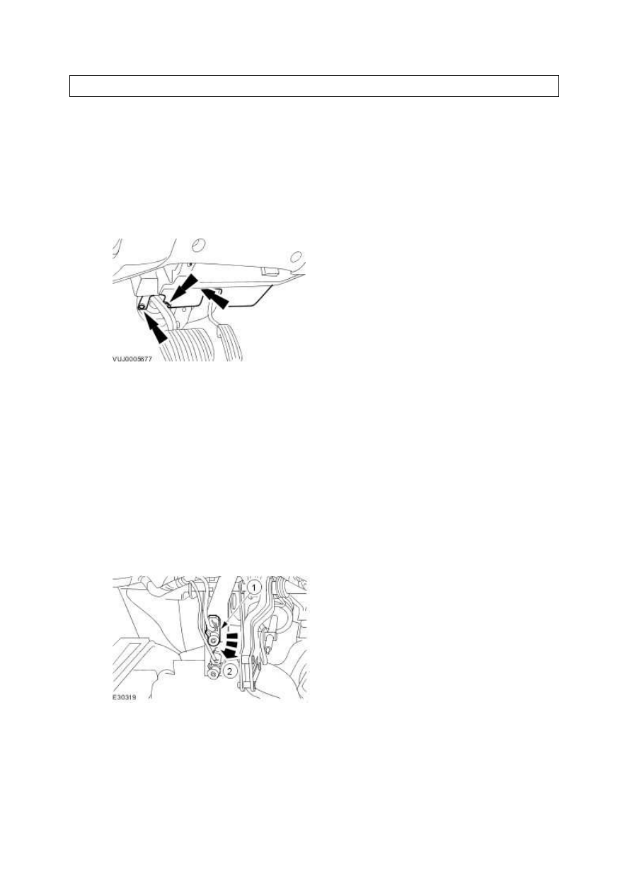
1 . Remove the driver side instrument panel lower panel.
2 . Reposition the driver seat to its maximum rearward position.
3 . Remove the speed control deactivator switch.
1) Disconnect the speed control deactivator switch electrical connector.
2) Remove the speed control deactivator switch.
Installation
1
.
To install, reverse the removal procedure.
www.
Нет комментариевНе стесняйтесь поделиться с нами вашим ценным мнением.
Текст