Jaguar XJ (X350). Manual — part 1117
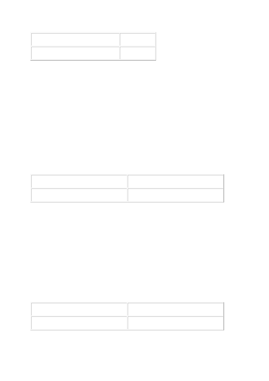
Fuel module connector FP06, harness side
Battery
Pin 13
Positive terminal
Is the resistance less than 10,000 ohms?
-> Yes
REPAIR the short circuit. For additional information, refer to the wiring diagrams. CLEAR the DTC, test
the system for normal operation.
-> No
GO to Pinpoint Test G532449t15.
G532449t15 : CHECK THE SENSOR A RESISTANCE EMPTY
1. Remove the right-hand fuel pump module.
Fuel Pump Module - 2.7L V6 - TdV6 (19.45.08) 2. Move the sensor float to it's lowest position. 3.
Measure the resistance between:
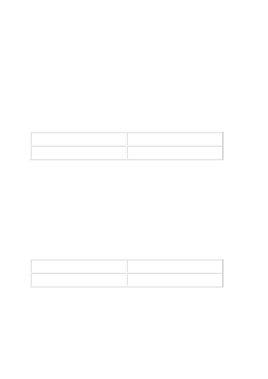
Fuel module connector FP06, component side Fuel module connector FP06, component side
Pin 12
Pin 13
Is the resistance 15 ohms?
-> Yes
GO to Pinpoint Test G532449t16.
-> No
INSTALL a new level sensor,
Fuel Level Sender RH - 2.7L V6 - TdV6 CLEAR the DTC, test the system for normal operation.
G532449t16 : CHECK THE SENSOR A RESISTANCE FULL
1. Move the sensor float to it's highest position. 2. Measure the resistance between:
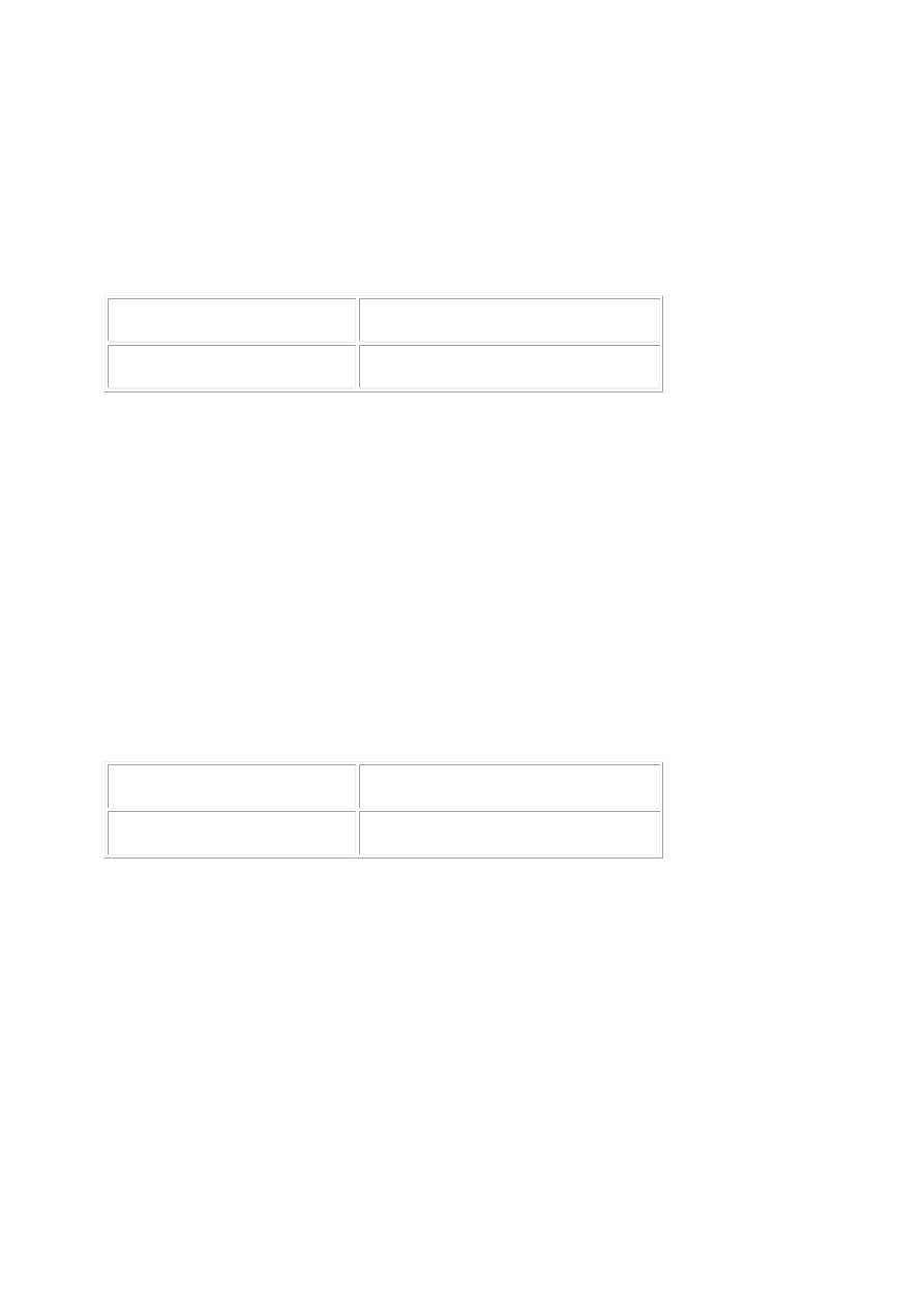
Fuel module connector FP06, component side Fuel module connector FP06, component side
Pin 12
Pin 13
Is the resistance 160 ohms?
-> Yes
GO to Pinpoint Test G532449t17.
-> No
INSTALL a new level sensor,
Fuel Level Sender RH - 2.7L V6 - TdV6 CLEAR the DTC, test the system for normal operation.
G532449t17 : CHECK THE SENSOR B RESISTANCE EMPTY
1. Remove the left-hand fuel pump module.
Fuel Pump Module - 2.7L V6 - TdV6 (19.45.08) 2. Move the sensor float to it's lowest position. 3.
Measure the resistance between:
Fuel module connector FP06, component side Fuel module connector FP06, component side
Pin 13
Pin 14
Is the resistance 15 ohms?
-> Yes
GO to Pinpoint Test G532449t18.
-> No
INSTALL a new level sensor,
Fuel Level Sender LH - 2.7L V6 - TdV6 CLEAR the DTC, test the system for normal operation.
G532449t18 : CHECK THE SENSOR B RESISTANCE FULL
1. Move the sensor float to it's highest position. 2. Measure the resistance between:
Fuel module connector FP06, component side Fuel module connector FP06, component side
Pin 13
Pin 14
Is the resistance 160 ohms?
-> Yes
GO to Pinpoint Test G532449t6.
-> No
www.
INSTALL a new level sensor,
Fuel Level Sender LH - 2.7L V6 - TdV6 CLEAR the DTC, test the system for normal operation.
G532449t6 : CHECK THE SIGNAL CIRCUIT BETWEEN THE REM AND LEVEL
SENSOR A FOR HIGH RESISTANCE
1. Disconnect the REM electrical connector, CR04. 2. Measure the resistance between CR04, pin 15
(WR) and FP06, pin 12 (WR).
REM connector CR04, harness side Fuel module connector FP06, harness side
Pin 15
Pin 12
Is the resistance greater than 5 ohms?
-> Yes
REPAIR the high resistance circuit. For additional information, refer to the wiring diagrams. CLEAR the
DTC, test the system for normal operation.
-> No
GO to Pinpoint Test G532449t9.
G532449t9 : CHECK THE SIGNAL CIRCUIT BETWEEN THE REM AND LEVEL
SENSOR B FOR HIGH RESISTANCE
1. Measure the resistance between:
REM connector CR04, harness side Fuel module connector FP06, harness side
Pin 16
Pin 14
Is the resistance greater than 5 ohms?
-> Yes
REPAIR the high resistance circuit. For additional information, refer to the wiring diagrams. CLEAR the
DTC, test the system for normal operation.
-> No
GO to Pinpoint Test G532449t12.
G532449t12 : CHECK THE SIGNAL RETURN CIRCUIT BETWEEN THE REM
AND LEVEL SENSORS FOR HIGH RESISTANCE
1. Disconnect the REM electrical connector, CR11. 2. Measure the resistance between:
REM connector CR11, harness side Fuel module connector FP06, harness side
Pin 23
Pin 13
Is the resistance greater than 5 ohms?
-> Yes
REPAIR the high resistance circuit. For additional information, refer to the wiring diagrams. CLEAR the
DTC, test the system for normal operation.
-> No
CHECK for DTCs indicating another cause of the complaint.
Electronic Engine Controls - VIN Range: G45704->G99999 For vehicles with 3.0L engines and
Electronic Engine Controls - VIN Range: G45704->G99999 For vehicles with 3.5L and 4.2L engines.
PINPOINT TEST G532449p5 : ECM TO
REM DRIVE CIRCUIT (V6 AND V8
VEHICLES WITHOUT
SUPERCHARGER)
G532449t23 : CHECK THE ECM TO REM DRIVE CIRCUIT FOR SHORT CIRCUIT
TO GROUND
1. Disconnect the REM electrical connector, CR11. 2. Measure the resistance between:
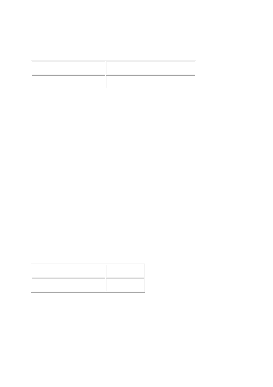
REM connector CR11, harness side
Battery
Pin 19
Negative terminal
Is the resistance less than 10,000 ohms?
-> Yes
REPAIR the short circuit. For additional information, refer to the wiring diagrams. CLEAR the DTC, test
the system for normal operation.
-> No
www.
Нет комментариевНе стесняйтесь поделиться с нами вашим ценным мнением.
Текст