Engines Iveco C87 / Cursor 87. Manual — part 31

115891
47585
Figure 74
Figure 75
- Through miller 99394044 (1) and bushing 99394045 (2),
ream the injector seat in the case (3), check the injector
protrusion from the cylinder head plane which must be
1.2 to 1.5 mm.
Using dial gauge (1), check the protrusion of the injector (2)
which must be 1.2 to 1.5 mm.
Checking protrusion of injectors
114056
Figure 76
INSTALLATION DIAGRAM FOR
INJECTOR CASE
SECTION 4 - OVERHAUL AND TECHNICAL SPECIFICATIONS
39
F2C CURSOR ENGINES
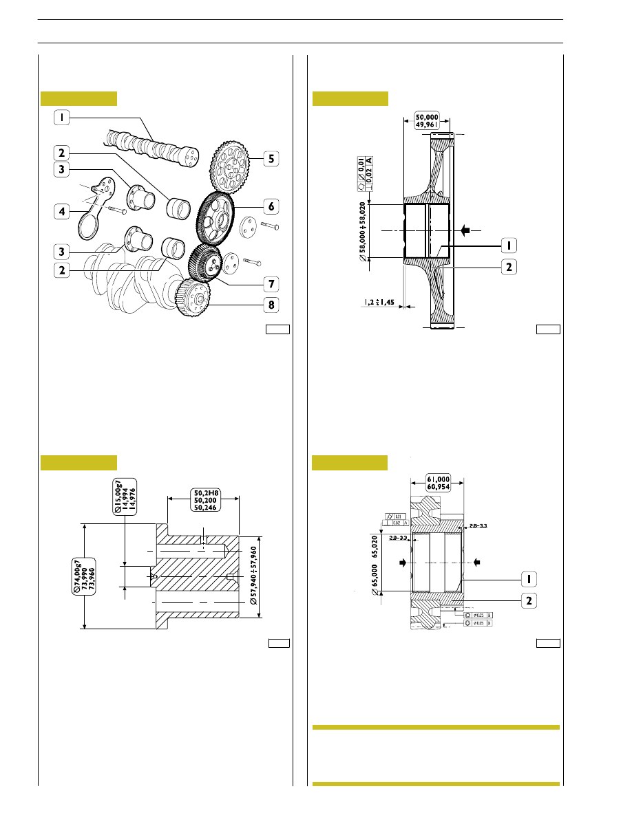
TIMING CONTROL COMPONENT PARTS
1. Camshaft - 2. Bushing - 3. Pin - 4. Articulated rod -
5. Camshaft control gear - 6. Idler gear - 7. Twin idler gear
- 8. Drive shaft driving gear.
114210
114211
Rated assembling play between idler gear bushings and pins:
0.040
÷ 0.080 mm.
5412
TIMING GEAR
Camshaft drive
541253
Intermediate gear pin
86926
541252
Idler gear
541252
Twin idler gear
541254
Replacing the bushings
Bushings (1, Figures 78-79) can be replaced when they are
worn. Put up the bushing, then grind it so as to bring it to a
dimension of
∅ 65.010 ± 0.10 mm.
Bushing fitting in gears (2, Figures 78-79) must be
performed in arrow direction, placing them as
shown in figures.
Figure 77
Figure 78
Figure 79
Figure 80
NOTE
114212
40
SECTION 4 - OVERHAUL AND TECHNICAL SPECIFICATIONS
F2C CURSOR ENGINES
Base - June 2007
47506
47505
47507
Figure 81
Figure 82
Figure 83
541210
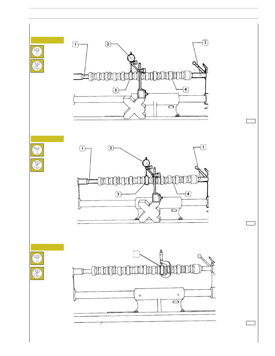
Camshaft
541211
Checking cam lift and pin alignment
When the camshaft (4) is on the tailstock (1), check alignment of supporting pin (3) using a centesimal gauge (2); it must not exceed
0.030 mm.
If misalignment exceeds this value, replace the shaft.
In order to check installation clearance, measure bush inner diameter and camshaft pin (1) diameter; the real clearance is obtained
by their difference.
If clearance exceeds 0.150 mm, replace bushes and, if necessary, the camshaft.
Place the camshaft (4) on the tailstock (1) and check cam lift (3) using a centesimal gauge (2); values are shown in table on page
9.
1
SECTION 4 - OVERHAUL AND TECHNICAL SPECIFICATIONS
41
F2C CURSOR ENGINES

The bush surfaces must not show any sign of seizing or
scoring; if they do replace them.
114213
Figure 84
Figure 85
MAIN DATA - CAMSHAFT AND TOLERANCES
The surfaces of shaft supporting pin and cams must be extremely smooth; if you see any sign of seizing or scoring, replace the
shaft and the relative bushes.
MAIN DATA - CAMSHAFT BUSHES AND RELATIVE BLOCK SEATS
* Bush inner diameter after installation
541213
Bushes
Measure the bush inner diameters with a baremeter and replace
them, if the value measured exceeds the tolerance value.
To take down and fit back the bushes, use the proper tool
99360487.
114214
42
SECTION 4 - OVERHAUL AND TECHNICAL SPECIFICATIONS
F2C CURSOR ENGINES
Base - June 2007
TOLERANCE CHARACTERISTIC
SYMBOL
ORIENTATION
Perpendicularity
⊥
POSITION
Concentricity or coaxial alignment
OSCILLATION
Circular oscillation
↗
IMPORTANCE CLASS ASSIGNED TO PRODUCT CHARACTERISTICS
SYMBOL
CRITICAL
©
IMPORTANT
⊕
SECONDARY
⊝
Нет комментариевНе стесняйтесь поделиться с нами вашим ценным мнением.
Текст