Engines Iveco C87 / Cursor 87. Manual — part 32
70000
114215
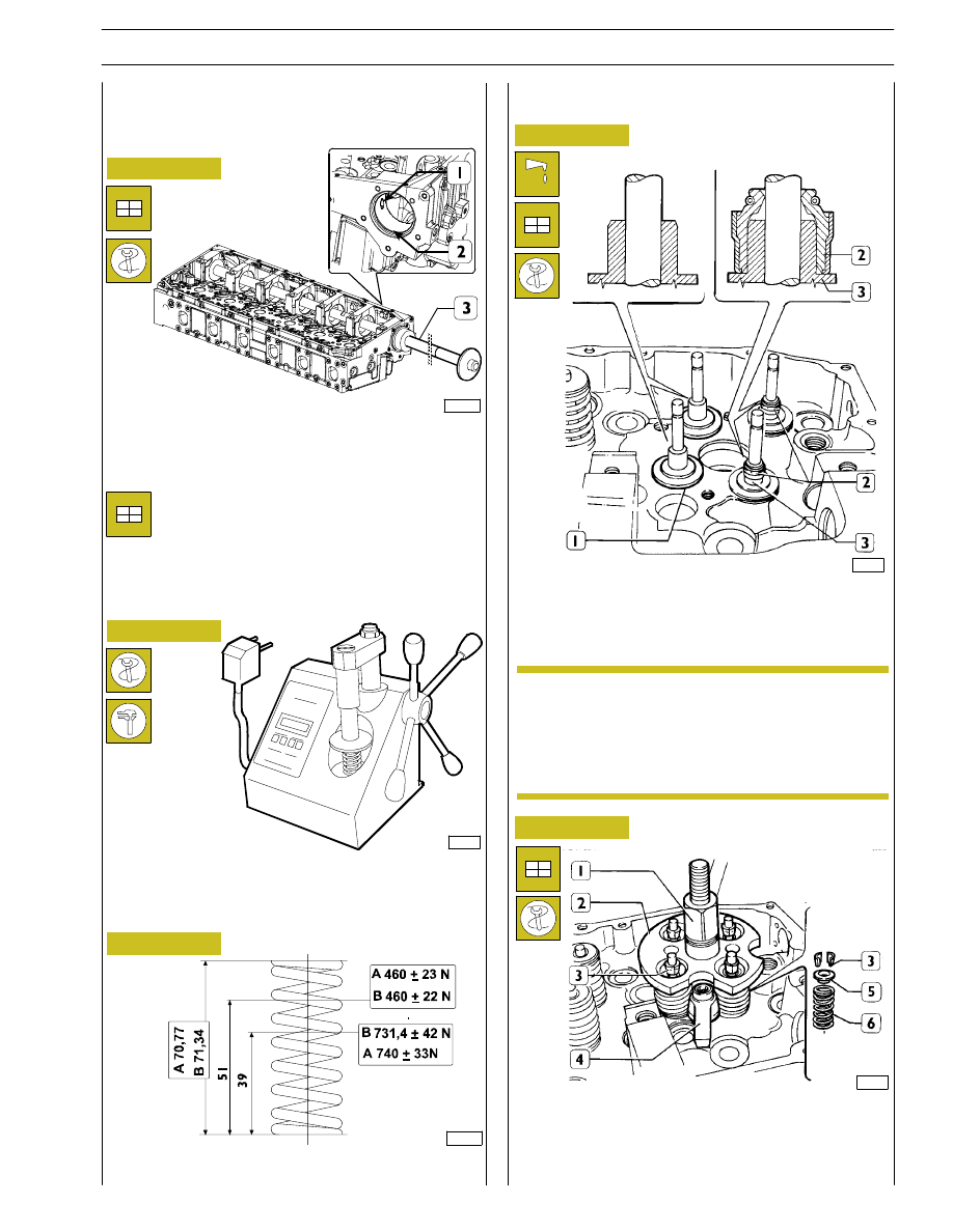
MAIN DATA TO CONTROL EXHAUST AND
DISCHARGE VALVE SPRING
Lubricate the valve stem and insert the valves in the
respective valve guides; fit the lower caps (1). Use tool
99360329 to fit the oil seal (2) on the valve guides (3) of the
exhaust valves; then, to fit the valves, proceed as follows.
- fit springs (6) and the upper plate (5);
- apply tool 99360264 (2) and block it with bracket (4);
tighten the lever (1) until cotters are installed (3),
remove tool (2).
540665
VALVE SPRINGS
Fitting the valves and oil seal ring
114280
Use tool 99360505 (3) fitted as shown in fig. to remove
bushings (2).
Accurately position beater during removal phase.
Before fitting, check valve spring flexibility using specific tool.
Compare the load and elastic deformation data with those
of the new springs given in the following figure.
Figure 86
Figure 87
Figure 88
Figure 89
87051
Should valves not have been overhauled or
replaced, remount them according to numbering
performed on dismounting.
Intake valves are different form exhaust valves in
that they have a notch placed at valve head centre.
NOTE
Use beater 99360505 to change bushings
Removal
Valve closed
Valve open
Fitting
For fitting, reverse operations performed for
removal, with care to make lube hole (1), drilled on
bushing, coincide with corresponding hole in housing.
Figure 90
86290
SECTION 4 - OVERHAUL AND TECHNICAL SPECIFICATIONS
43
F2C CURSOR ENGINES
114216
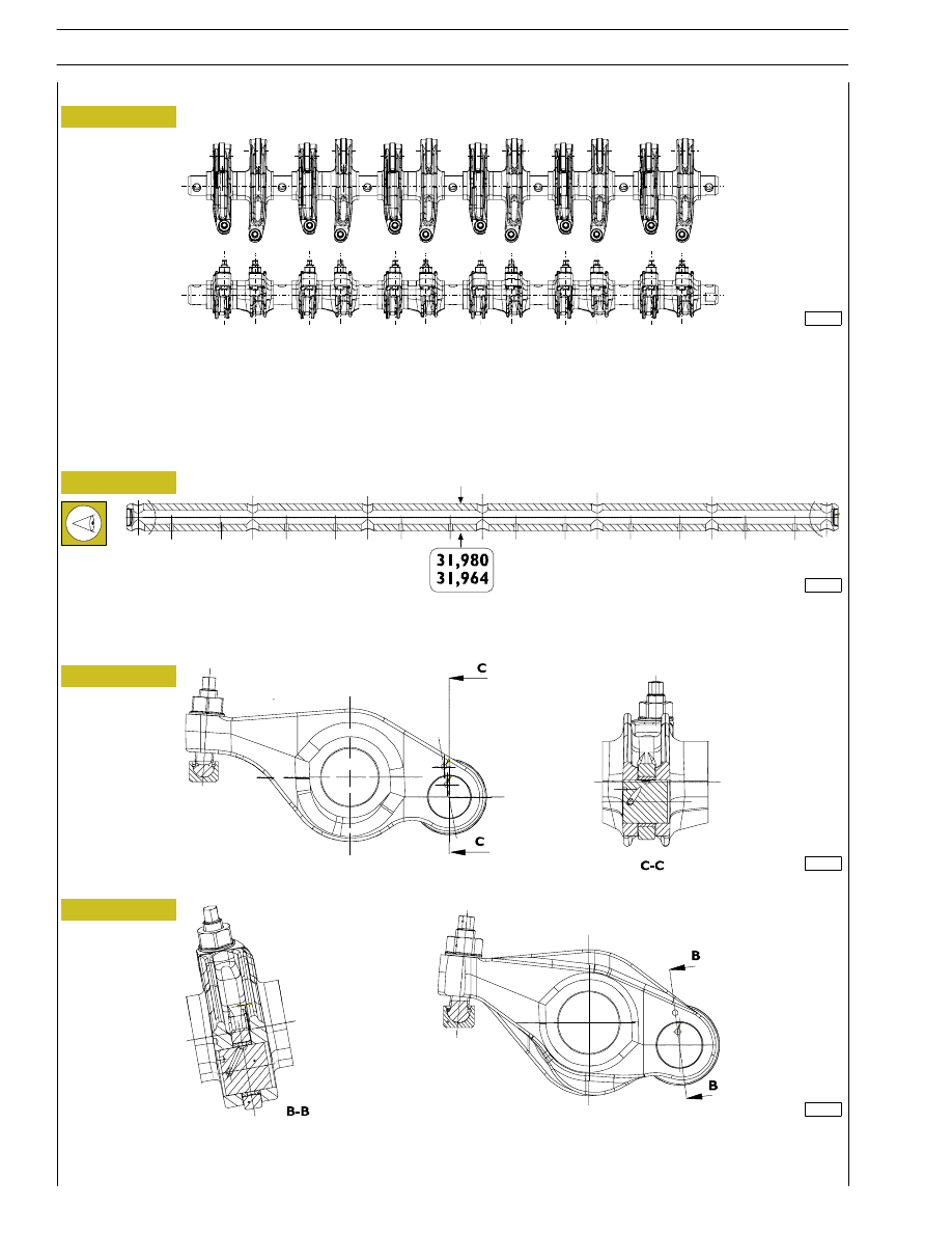
The camshaft eccentric elements control the 12 valve rocker arms directly. Valve control rocker arms are fitted directly on rocker
arm shaft. Rocker arms slide directly on cam profiles by rollers. The other end operates on a crosspiece laid directly on the two
valve rods. A pad is placed between rocker arm adjustment screw and crosspiece. Two lube ducts are machined inside rocker
a rms. Rocker arms shaft runs through the cylinder head; it must be removed to reach all units below.
Figure 91
Figure 92
Figure 93
Figure 94
EXHAUST VALVES ROCKER
The bush surfaces must not show any trace of scoring of excessive wear; otherwise, replace bushes or the whole rocker.
DISCHARGE VALVE ROCKER
Rocker
Check that the surface of the shaft shows no scoring or signs of seizure; if it does, replace it.
MAIN DATA OF THE ROCKER ARM SHAFT
Shaft
5412
ROCKER SHAFT
114217
114219
114218
44
SECTION 4 - OVERHAUL AND TECHNICAL SPECIFICATIONS
F2C CURSOR ENGINES
Base - June 2007

SECTION 4 - OVERHAUL AND TECHNICAL SPECIFICATIONS
45
F2C CURSOR ENGINES
TIGHTENING TORQUES
PART
TORQUE
Nm
kgm
Pipe union for piston cooling nozzle
M12X1.5
35
± 2
3.5
± 0.2
Heat exchanger retaining screws
63
± 7
6.3
± 0.7
Plug
125
± 15
12.5
± 1.5
Spacer and oil sump fastening screws
M10
41.5
± 3.5
4.1
± 0.3
Gearcase fastening screws to cylinder block:
M10x1.25
41.5
± 3.5
4.1
± 0.3
M12x1.75
63
± 7
6.3
± 0.7
M8x1.25
23.5
± 1.5
2.3
± 1.5
Cylinder head fastening screw
♦
First stage
pre-tightening
50
5
Second stage
pre-tightening
100
10
Third stage
angle closing
90
°
Fourth stage
angle closing
75
°
Rocker arm shaft fastening screw
104,5
± 10,5
104.5
± 10.5
10,4
± 1
10.4
± 1
Locknut for rocker arm adjusting screw
♦
39
± 5
3.9
± 5
Electroinjector retaining bracket screws
♦
M10
41.5
± 3.5
4.1
± 0.3
Shoulder plate fastening screws to head
♦
20
± 2
2
± 0.2
Engine support bracket fastening screws to cylinder head
74
± 8
7.4
± 0.8
Gear fastening screws to camshaft
•
First stage
pre-tightening
25
2.5
Second stage
pre-tightening
45
°
Phonic wheel fastening screws to distribution gear
8.5
± 1.5
0.8
± 0.1
Exhaust pipe fastening screws
•
pre-tightening
tightening
40
± 5
70
± 5
4
± 0.5
7
± 0.5
Connecting rod cap fastening screws:
♦
First stage
pre-tightening
50
5
Second stage
pre-tightening
90
°
Engine flywheel fastening screws
♦
M18x1.5x72
First stage
pre-tightening
120
12
Second stage
pre-tightening
90
°
Flywheel pulley fastening screws to crankshaft
♦
First stage
pre-tightening
70
7
Second stage
pre-tightening
50
°
Main journal retaining screws
♦
First stage
pre-tightening
140
14
Second stage
pre-tightening
60
° + 60°
♦ Lubricate with oil MOLYKOTE before assembly
•
Lubricate with graphitized oil before assembly

46
SECTION 4 - OVERHAUL AND TECHNICAL SPECIFICATIONS
F2C CURSOR ENGINES
Base - June 2007
TORQUE
Nm
kgm
Damper flywheel fastening screws
♦
115
± 15
11.5
± 1.5
Idler gear pin fastening screws
♦
First stage
pre-tightening
30
3
Second stage
angle closing
90
°
Idle gear link rod fastening screw
24.5
± 2.5
2.4
± 0.2
Oil pump fastening screw
24.5
± 2.5
2.4
± 0.2
Oil pump suction rose fastening screw
24.5
± 2.5
2.4
± 0.2
Front cover fastening screw to cylinder block
19
± 3
1.9
± 0.3
Control unit fastening screw to cylinder block
19
± 3
1.9
± 0.3
Fuel filter support fastening screw to cylinder head
♦
24.5
± 2.5
2.4
± 0.2
Screw securing the engine support to the wheelcase
♦
First stage
pre-tightening
100
10
Second stage
angle closing
60
°
Turbo-compressor fastening screws and nuts
•
pre-tightening
tightening
35
± 5
46
± 2
3.5
± 0.5
4.6
± 0.2
Water pump fastening screw to cylinder block
24.5
± 2.5
2.4
± 0.2
Pulley fastening screw to hub
55
± 5
5.5
± 0.5
Rocker arm cover fastening screws
8.5
± 1.5
0.8
± 0.1
Thermostat box fastening screws to cylinder head
24.5
± 2.5
2.4
± 0.2
Automatic tightener fastening screws to cylinder block
45
± 5
4.5
± 0.5
Fixed tightener fastening screws to cylinder block
105
± 5
10.5
± 0.5
Fan support fastening screws to cylinder block
24.5
± 2.5
2.4
± 0.2
Starter fastening screws
44
± 4
4
± 0.4
Air heater on cylinder head
30
± 3
5
± 0.5
Hydraulic power steering pump gear fastening nut
105
± 5
10.5
± 0.5
Air conditioner compressor fastening screw to support
24.5
± 2.5
2.4
± 2.5
Alternator support superior fastening screw
71.5
± 4.5
7.1
± 0.4
Alternator bracket fastening screw to cylinder block
24.5
± 2.5
2.4
± 0.2
Water pipe unions
35
3.5
Water temperature sensor
32.5
± 2.5
3.2
± 0.2
♦ Lubricate with oil MOLYKOTE before assembly
•
Lubricate with graphitized oil before assembly
Нет комментариевНе стесняйтесь поделиться с нами вашим ценным мнением.
Текст