Engines Iveco C87 / Cursor 87. Manual — part 28

Make sure the piston does show any trace of seizing, scoring,
cracking; replace as necessary.
49023
47580
Figure 40
Figure 41
PISTON CONNECTING ROD ASSEMBLY
1. Connecting rod body - 2. Half bearings - 3. Connecting rod cap - 4. Cap fastening screws - 5. Split ring - 6. Scraper ring
with spiral spring - 7. Bevel cut sealing ring - 8. Trapezoidal sealing ring - 9. Piston pin - 10. Piston
Removal of the piston split rings (2) using the pliers 99360184
(1).
Removal
Pistons are equipped with three elastic rings: a sealing ring, a
trapezoidal ring and a scraper ring.
Pistons are grouped into classes A and B for diameter.
49024
Figure 42
Remove the piston pin split rings (2) using the round tipped
pliers (1).
5408
PISTON-CONNECTING ROD ASSEMBLY
SECTION 4 - OVERHAUL AND TECHNICAL SPECIFICATIONS
27
F2C CURSOR ENGINES

49025
32618
49026
Figure 43
Figure 44
Figure 45
Figure 46
Remove the piston pin (1).
If removal is difficult use the appropriate beater.
Measuring the diameter of the pistons
Measuring the gudgeon pin diameter (1) with a micrometer
(2).
Conditions for correct gudgeon pin-piston
coupling
Lubricate the pin (1) and the relevant housing on the piston
hubs with engine oil; piston must be inserted with a slight
finger pressure and it should not come out by gravity.
47584
Using a micrometer (2), measure the diameter of the piston
(1) to determine the assembly clearance; the diameter should
be measured at the specified value.
28
SECTION 4 - OVERHAUL AND TECHNICAL SPECIFICATIONS
F2C CURSOR ENGINES
Base - June 2007
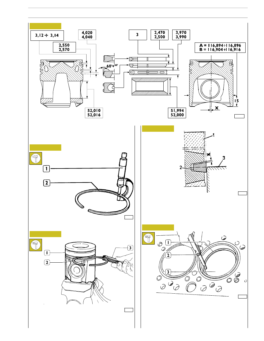
MAIN DATA OF PISTON, SNAP RINGS AND PIN
X = 0,6
± 0,15
• The dimension is measured on a ∅ of 113 mm
16552
3513
Figure 47
Check the thickness of the piston ring (2) using a micrometer
(1).
The sealing ring (2) of the 1º cavity is trapezoidal. Clearance
“X” between the sealing ring and its housing is measured by
placing the piston (1) with its ring in the cylinder barrel (3),
so that the sealing ring is half-projected out of the cylinder
barrel.
540842
Piston rings
114053
16552
Check the clearance between the sealing rings (2) and the
relative piston housings (1) using a thikness gauge (3).
36134
Check the opening between the ends of the sealing rings (1),
using a thickness gauge (2), entered in the cylinder barrel (3).
If the distance between ends is lower or higher than the value
required, replace split rings.
Figure 48
Figure 49
Figure 50
Figure 51
SECTION 4 - OVERHAUL AND TECHNICAL SPECIFICATIONS
29
F2C CURSOR ENGINES

114054
Figure 52
MAIN DATA - BUSH, CONNECTING ROD, PIN AND HALF-BEARINGS
* Values to be obtained after installing the bush
When fitting the connecting rods, check that all of them are of same weight class and from the same supplier. The
connecting rod/cap is of ”torn” type; before assembly verify that the connecting rod is not damaged. Each connecting
rod can assembled with the relative cap only. If the cap is assembled on the reverse side, the connecting rod must be
rejected.
540830
CONNECTING ROD
1 Between the connecting rod bush and the connecting rod profile there must be a distance > 0.4 mm.
2 On the external breaking line, gap area allowed must be < 5 mm
2
.
3 No cracks are allowed in the threaded area.
30
SECTION 4 - OVERHAUL AND TECHNICAL SPECIFICATIONS
F2C CURSOR ENGINES
Base - June 2007
Нет комментариевНе стесняйтесь поделиться с нами вашим ценным мнением.
Текст