Engines Iveco C87 / Cursor 87. Manual — part 27

Figure 29
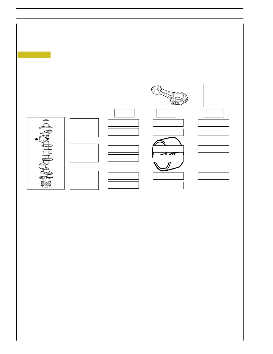
SELECTING THE BIG END BEARING SHELLS
(JOURNALS WITH NOMINAL DIAMETER)
There are 4 references on the connecting rod casing in the
positions illustrated:
1.
Coloured mark for identifying the weight
2.
Coloured mark for identifying the diameter grade
3.
Positioning stud visible from the front of the engine
4.
Progressive number for identifying the connecting rod
The number, indicating the class of diameter of the bearing
shell seat may be 1, 2 o 3.
Determine the type of big end bearing to fit on each journal
by following the indications in the table (Figure 30).
47557
STD.
1
2
3
green
green
red
green
red
red
red
green
green
yellow
yellow
yellow
green
green
yellow
green
green
green
Class
Figure 30
The identification colours of the marks are given in
the table on page 31.
NOTE
1
yellow
2
green
3
blue
SECTION 4 - OVERHAUL AND TECHNICAL SPECIFICATIONS
23
F2C CURSOR ENGINES
green/black
Selection of connecting rod half-bearings (rectified pins)
If pins have been rectified, the procedure described must be applied.
In this case, (for each undersizing) determine the tolerance field the new big end pins belong to, and install the half-bearings
identified according to the relative table.
-0.127
1
2
3
81.789
81.799
green/black
green/black
green/black
yellow/black
yellow/black
yellow/black
red/black
green/black
green/black
green/black
yellow/black
red/black
red/black
red/black
green/black
green/black
green/black
81.799
81.809
81.809
81.819
1
2
3
red/black =
mm 2.057 to 2.065
green/black =
mm 2.065 to 2.073
Figure 31
green/black =
mm 2.073 to 2.081
24
SECTION 4 - OVERHAUL AND TECHNICAL SPECIFICATIONS
F2C CURSOR ENGINES
Base - June 2007
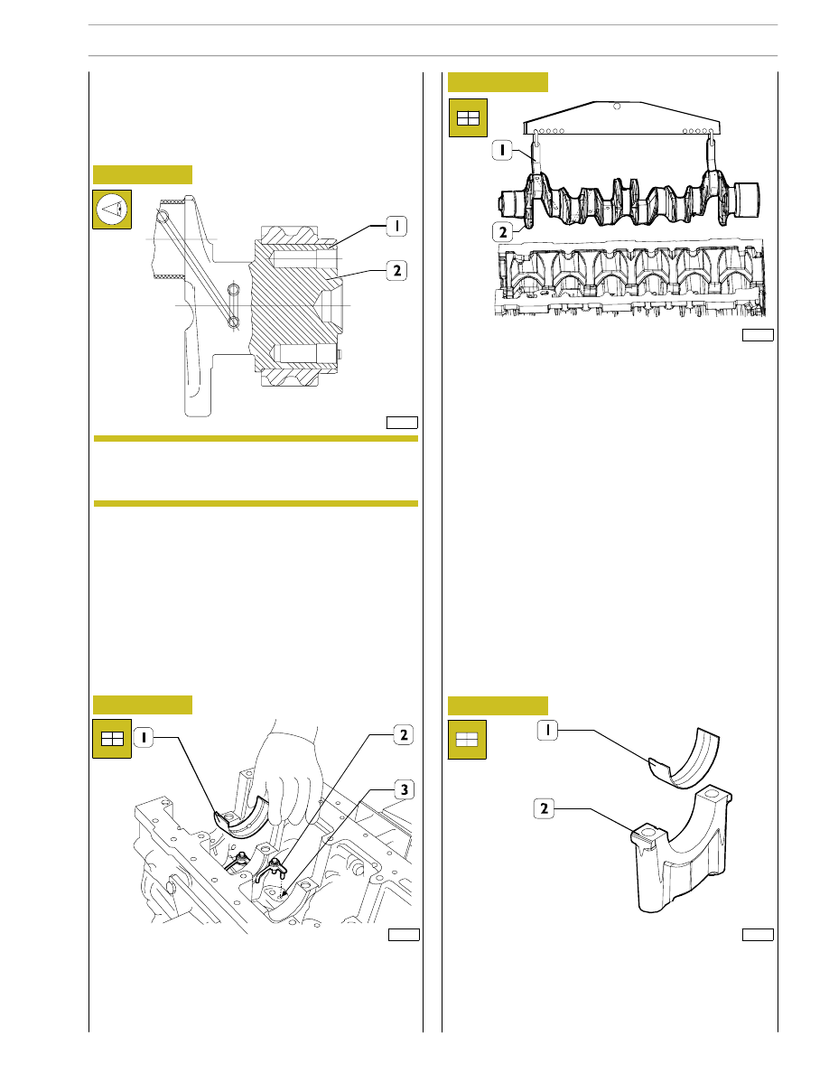
Place bearing halves (1) on main journals (2).
Check the installation clearance between the main journals
and the relative bearings as follows.
Using the hoist and hook 99360500 (1) mount the driving
shaft (2).
After fitting the gear (1) on the crankshaft (2), heat it for
~15 minutes in an oven at temperature not higher than
180
°C.
Let them cool down after the installation.
If changing the pin (3), after fitting it on, check it protrudes
from the crankshaft as shown in the figure.
115883
114049
114034
114050
Figure 32
Figure 33
Figure 34
Figure 35
Fit the oil jets (2) aligning the dowel with the opening (3) in
the crankcase.
Position the half-bearings (1) and the thrust washers on the
main journal supports as illustrated in Figure 18.
540815
Replacing the timing control gear
and the oil pump
Check that the teeth of the gears are not damaged or worn,
otherwise remove them using the appropriate extractor.
540811
Checking main journal installation
clearance
Before fitting the gear, spread Loctite type 603 on
approx. 5 mm wide band on crankshaft, at 30 mm
from contact surface.
NOTE
SECTION 4 - OVERHAUL AND TECHNICAL SPECIFICATIONS
25
F2C CURSOR ENGINES
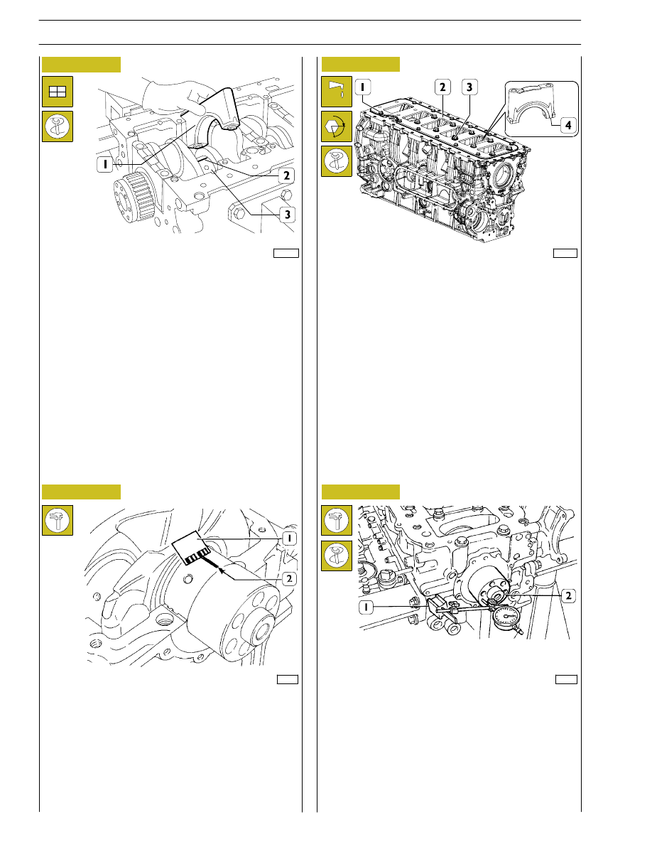
End float is checked by placing a magnetic dial gauge (1) on
the crankshaft (2), as shown in the figure.
If the value obtained is higher than specified, replace the rear
thrust half-bearings and repeat this check.
- Position the main journal caps (4) and fit the
strengthening plate (2) following the procedure
described:
- Tighten the inner bolts and then the outer bolts by hand
starting from main journal ”7” and continuing until main
journal ”1”.
- Tightening the bolts using torque wrench always starting
from main journal ”7” and continuing until main journal
”1”:
1
st
stage: 140 Nm
2
nd
stage 60
°+60°
Fit sized wire sections (2) on crankshaft (3) parallel to
longitudinal axis.
Install main journals (1).
114051
47579
114615
47588
Figure 36
Figure 37
Figure 38
Figure 39
- Remove main journals.
The clearance between the main bearings and the journals
is obtained by comparing the calibrated wire length (2) at the
maximum deflection point, with the calibrated scale on the
coating (1) containing the calibrated wire.
Numbers shown on the scale specify the clearance in
coupling millimeters.
If the clearance obtained is different from the clearance
required, replace the half-bearings and repeat this check.
Checking crankshaft end float
α
26
SECTION 4 - OVERHAUL AND TECHNICAL SPECIFICATIONS
F2C CURSOR ENGINES
Base - June 2007
Нет комментариевНе стесняйтесь поделиться с нами вашим ценным мнением.
Текст