Engines Iveco C87 / Cursor 87. Manual — part 6

114250
Figure 21
Figure 22
Figure 23
Thermostat
The water pump consists of: rotor, shaft with bearing,
T-gasket and drive pulley with dust shield.
Check that the pump body has no cracks or water
leakage; if it does, replace the entire water pump.
CROSS-SECTION OF THE WATER PUMP
View of thermostat operation
45357
Water circulating in the engine
Water leaving the thermostat
45358
Check the thermostat works properly; replace it if in doubt.
Temperature of start of travel 84
°C ±2°C.
Minimum travel 15 mm at 94
°C ±2°C.
Water pump
NOTE
TO THE HEATER
TO BY-PASS
FROM THE HEAD
TO EXPANSION TANK
FROM THE HEAD
TO RADIATOR
TO THE HEATER
16
SECTION 1 - GENERAL SPECIFICATIONS
F2C CURSOR ENGINES
Base - June 2006
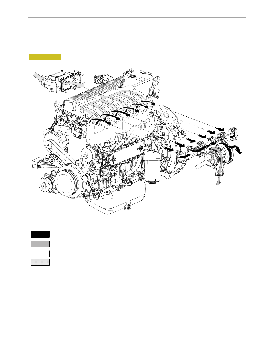
Figure 24
TURBOCHARGING
The turbocharging system consists of:
- air filter;
- Wastegate turbocharger.
114251
Exhaust gas
Inlet air
Compressed air (hot)
Intake compressed air
SECTION 1 - GENERAL SPECIFICATIONS
17
F2C CURSOR ENGINES

EGR EXHAUST GAS RECYCLE SYSTEM
The exhaust gas can be partially recycled to cylinders to reduce maximum temperature values of combustion that produce nitro-
gen oxides (NOx).
The exhaust gas recycle system (EGR) reduces combustion temperature and therefore is an efficient NOx emission control
system.
INTERNAL EGR OPERATING ON SUCTION VALVES
The specific design of suction cams of the internal EGR system allows part of exhaust gas to be recycled to engine cylinders.
This type of EGR, called internal EGR, is not equipped with any electronic control, the system is always active. Its configuration
requires no additional parts such as control valves, pipelines or heat exchangers therefore engine profile remains unchanged
Besides main lobe, suction cam has an additional lobe (3) as to configuration without EGR. During concerned cylinder exhaust
phase, this lobe allows a shaft advanced opening of intake valve (*). In this way, part of the exhaust gas is trapped in the suction
duct and later, during cylinder suction phase, this gas is recycled to cylinder inlet for combustion phase..
Figure 25
114026
1. Exhaust cams - 2. Suction cams - 3. EGR lobe - S. Exhaust ducts - A. Intake ducts
Y : Valve lift in mm
X: Crankshaft adjustment
in degrees
– Valve tolerance = 0 mm
— — Valve tolerance = 0,4 mm
18
SECTION 1 - GENERAL SPECIFICATIONS
F2C CURSOR ENGINES
Base - June 2006

Figure 1
114252
SUPPLY
The Common Rail supply system is equipped with a special pump that maintains fuel at constant high pressure regardless
from phase and cylinder under injection and accumulated in an common duct shared by all electric injectors.
Therefore, fuel at injection pressure, calculated by ECU, is always available at electric injection inlet.
When the solenoid valve of an injector is energized by ECU, in related cylinder the injection of fuel taken directly from the
rail takes place.
Return
circuit
Supply
circuit
SECTION 1 - GENERAL SPECIFICATIONS
3
F2C CURSOR ENGINES
Нет комментариевНе стесняйтесь поделиться с нами вашим ценным мнением.
Текст