Engines Iveco C87 / Cursor 87. Manual — part 7
114253
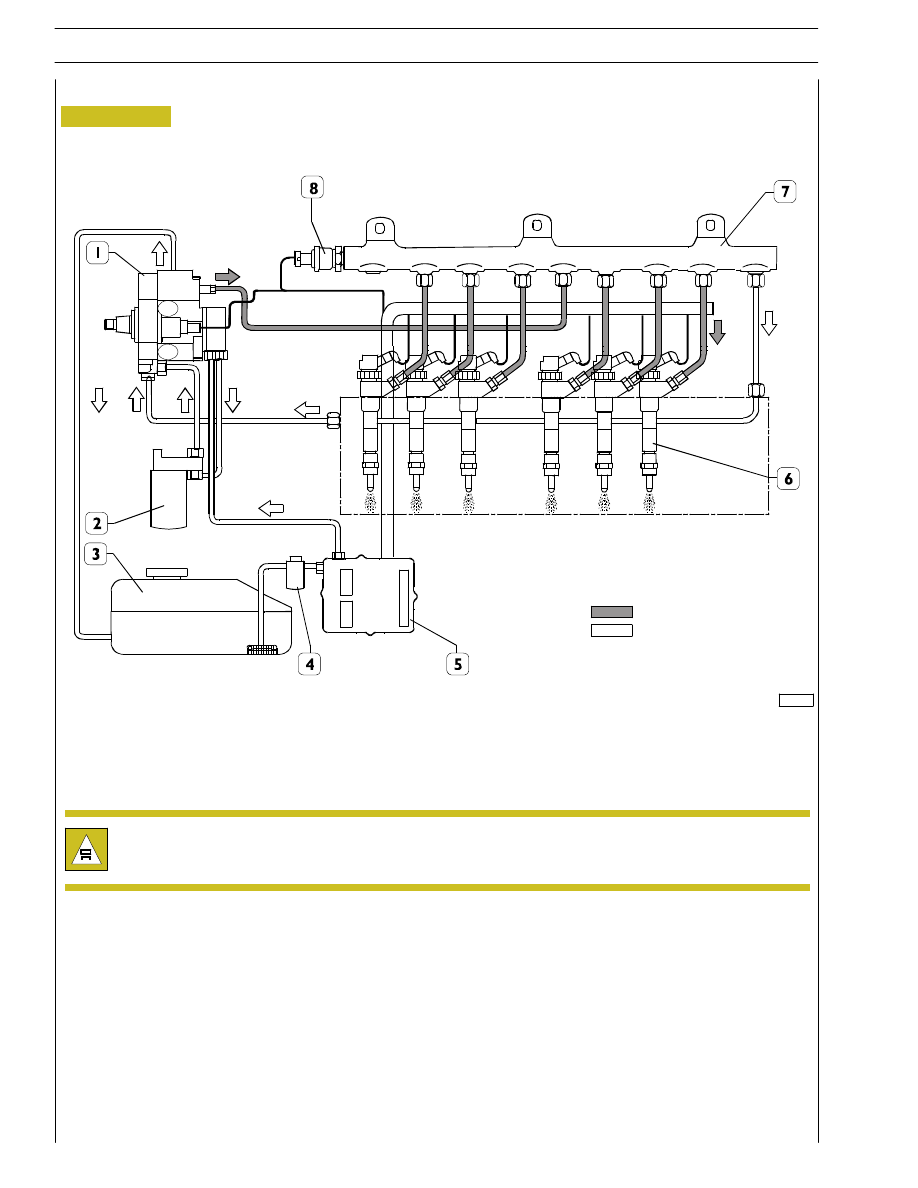
Figure 2
1. High-pressure pump - 2. Fuel filter - 3.Tank - 4. Fuel pre-filter - 5.ECU - 6. Electric injectors - 7.Common Rail -
8. Pressure sensor
FUEL SUPPLY DIAGRAM
High pressure
Low pressure
After high-pressure pipeline installation, during the following 20 hours of work, frequently check engine oil level.
(IT MUST NOT INCREASE).
4
SECTION 1 - GENERAL SPECIFICATIONS
F2C CURSOR ENGINES
Base - June 2007
MECHANICAL SUPPLY PUMP
Gear pump, fitted on the rear side of the high pressure pump
and used to supply it.
It is controlled by high pressure pump shaft.
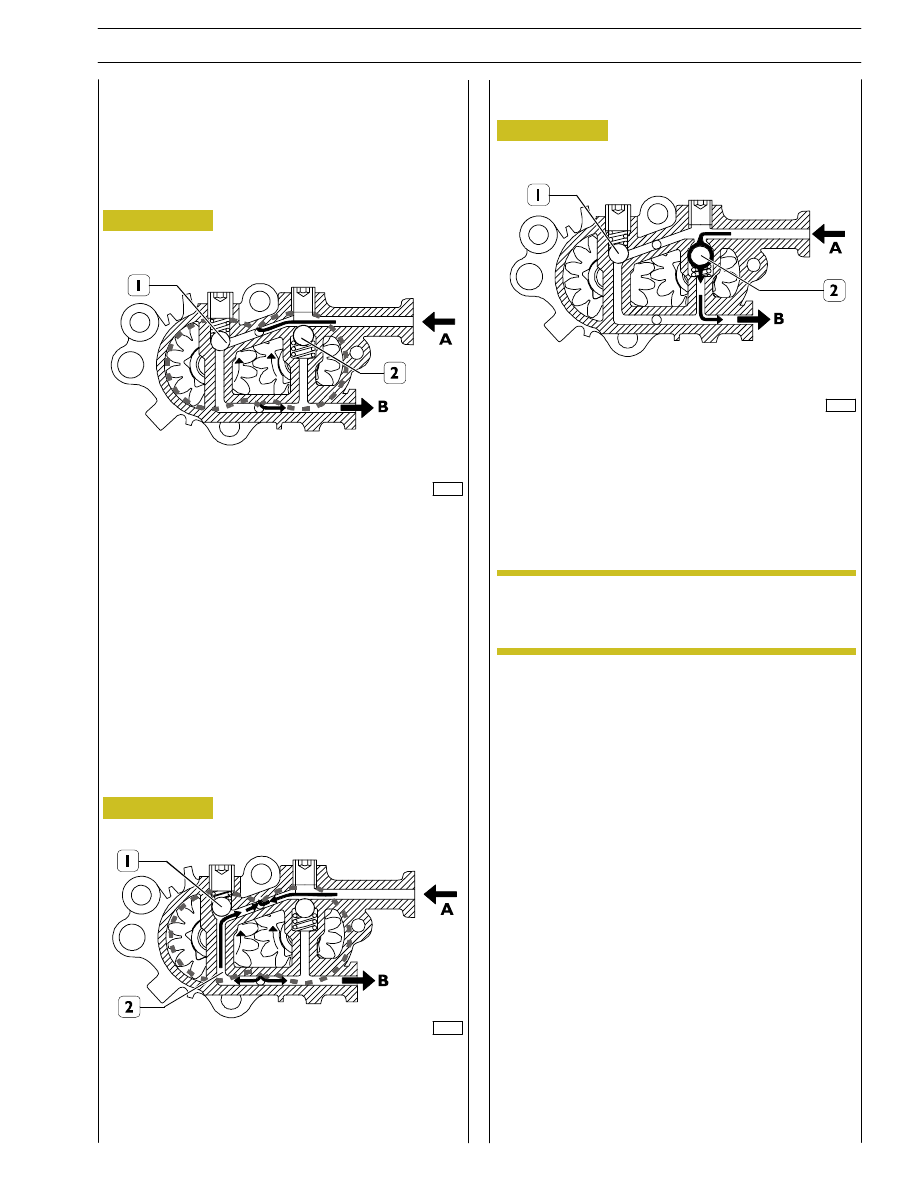
Normal operating conditions
Figure 3
72592
A Fuel inlet from tank, B fuel outlet to filter, 1-2 by-pass valves
in close position
Overpressure condition at outlet
Figure 4
72593
The by-pass valve (1) cuts in when overpressure is generated
at outlet B. The existing pressure, overcoming valve spring (1)
elastic strength, makes inlet and outlet communicating
through duct (2).
Figure 5
Drain conditions
72594
The by-pass valve (2) cuts in when, with engine off, the fuel
system shall be filled through the priming pump. In this
situation the by-pass valve (1) stays closed whereas by-pass
valve (2) opens due to inlet pressure, and fuel is drained out
through B.
The mechanical supply pump cannot be replaced
individually, therefore it cannot be removed from
the high pressure pump.
NOTE
SECTION 1 - GENERAL SPECIFICATIONS
5
F2C CURSOR ENGINES
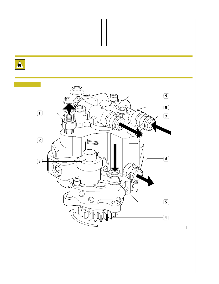
Figure 6
72595
1. Fuel outlet fitting to rail - 2. High-pressure pump - 3. Pressure regulator - 4. Control gear - 5. Fuel inlet fitting from filter -
6. Fuel outlet fitting to filter support - 7. Fuel inlet fitting from control unit heat exchanger - 8. Fuel outlet fitting from supply
pump to filter - 9. Mechanical supply pump
Pump with 3 radial pistons controlled by the timing gear,
without needing any setting. On the rear side of the high
pressure pump is fitted the mechanical supply pump
controlled by the high pressure pump shaft.
CP3 HIGH-PRESSURE PUMP
The following work must be carried out on the feed pump / high-pressure pump assembly:
- replacing the drive gear;
- replacing the pressure regulator.
6
SECTION 1 - GENERAL SPECIFICATIONS
F2C CURSOR ENGINES
Base - June 2007

70498
Figure 7
Every pumping unit is composed of:
- a piston (5) actuated by a three-lobe element (2) floating
on the pump shaft (6). The element (2), being floating on
a misaligned part of the shaft (6), when the shaft rotates,
does not rotate therewith but is only
1. Cylinder — 2. Three-lobe element — 3. Cap intake valve — 4. Ball delivery valve — 5. Piston — 6. Pump shaft —
7. Low-pressure fuel inlet — 8. Pumping elements supplying fuel ducts
HIGH-PRESSURE PUMP - INSIDE STRUCTURE
sec. B-B
sec. C-C
translated in a circular movement along a wider radius, with
the resulting alternate actuation of the three pumping
elements;
- cap intake valve (3);
- ball delivery valve (4).
SECTION 1 - GENERAL SPECIFICATIONS
7
F2C CURSOR ENGINES
Нет комментариевНе стесняйтесь поделиться с нами вашим ценным мнением.
Текст