Engines Iveco C87 / Cursor 87. Manual — part 45
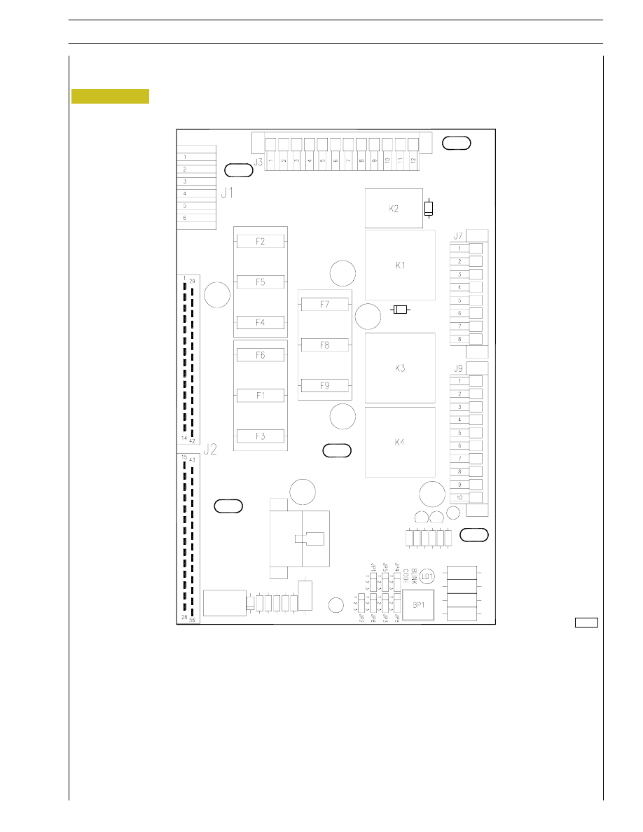
Figure 10
ENGINE INTERFACE BOX
Description
107437
LIST OF COMPONENTS
K1. Power relay with key inserted (+15) - K2. Starting phase signal relay - K3. Starting relay - K4. Relay for pre-heating
resistance enabling - JP1. Jumper to select frequency (jumper on 1-2= 60Hz - jumper on 2-3= 50Hz) - JP2. Jumper for
operating mode selection (bond on 1-2= diagnosis - bond on 2-3= normal operation) - JP3. Jumper to select cold start signal
connection (1-2= connected - 2-3= disconnected) - JP4. Jumper to select heat. function for cold starting (1-2= connected -
2-3= disconnected) - JP5. Jumper for Can Line selection (1-2= Can Line connected - 2-3= Can Line not connected) -
JP6. Not used - JP8. Not used - BP1. Switch for blink-code signal request - LD1. LED signalling blink/code -
F1. 10A fuse for starting engine - F2. 3A fuse for diagnostics - F3. 20A protection fuse for pre-heating resistance -
F4. 30A fuse for electronic control unit - F5. 10A fuse for control panel - F6. 5A fuse for cut-in +15 ON ECU - F7. 20A
protection fuse for fuel filter heater - F8. Not used - F9. Not used - J1. Connector for power connections - J2. Connector
for interface with engine control unit - J3. Connector for interface with control panel - J7. Connector for interface with
control panel - J9. Connector for interface with control panel.
25
CURSOR ENGINES G-DRIVE
SECTION 2 - G-DRIVE APPLICATION
Base - June 2007
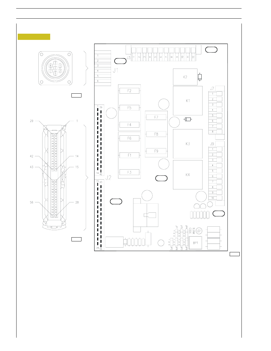
Figure 11
Connectors
107437
CONNECTOR J1 on engine — control panel interface box for power supply (GECURSOR300E/350E/400E)
1
To terminal 50 of starter motor
2
Supply from F3 for fuel filter heating resistance
3
Battery negative
4
Direct positive to battery
5
Spare
6
Spare
107438
107439
26
SECTION 2 - G-DRIVE APPLICATION
CURSOR ENGINES G-DRIVE
Base - June 2007
CONNECTOR J2 on engine — control panel interface box for EDC ECU connections
1
+15 from ignition key
2
12 jumper
3
Negative signal from oil low pressure pressure switch
4
Signal from water temperature sensor
5
Negative signal from water high temperature pressure switch
6
Signal from fuel zero level transmitter
7
Fuel low level signal
8
Supply of water presence in fuel sensor
9
Signal from water presence in fuel sensor
10
Ground of water presence in fuel sensor
11
Jumper with 37
12
Jumper with 2
13
Positive +30
14
Positive +30
17
Supply of water low level sensor
18
Signal from water low level sensor
19
Ground of water low level sensor
20
No recharge from alternator signal
22
Ground for diagnosis lamp
23
Positive signal for diagnosis lamp
25
Torque limiting resistance
27
Line K - diagnosis EDC
29
Negative signal from EDC system diagnostic switch
31
Signal from oil pressure sensor
32
Negative signal from water heater thermostat
33
Ground
37
Jumper with 11
40
Positive signal for excitation of contactor of fuel filter heater
41
Positive +30
42
Positive +30
46
Ground
47
Ground
48
Positive for cold start lamp
49
Positive for excitation of pre-heating contactor
50
Pre-heating contactor ground
53
Negative signal from EDC system diagnostic switch
54
Engine revs signal from EDC control unit
55
Line CAN L
56
Line CAN H
NOTA
Pins 1 and 2 of EDC ECU are connected to battery negative
27
CURSOR ENGINES G-DRIVE
SECTION 2 - G-DRIVE APPLICATION
Base - June 2007
CONNECTOR J3 inside the engine interface box for signals to control panel
1
Free
2
From the engine water temperature transmitter for signal to thermometer on control panel
3
From the low engine oil pressure switch for visual warning on control panel
4
From engine oil pressure switch for signal to pressure gauge on control panel
5
Free
6
To the key switch (+50) on control panel
7
From the alternator for battery charging visual indicator on control panel
8
From the low engine water level transmitter for visual warning on control panel
9
+15
10
From the water in fuel filter transmitter for visual warning on control panel
11
Free
12
Free
CONNECTOR J7 inside the engine interface box for signals to control panel
1
From the engine coolant high temp. thermostat for visual signal on control panel
2
CAN line L to the control panel
3
Positive to power control panel
4
Negative to power control panel
5
CAN line H to the control panel
6
From the engine water heater thermostat to the control panel
7
From the fuel level transmitter for visual warning on control panel
8
From the no fuel transmitter (opt)
CONNECTOR J9 inside the engine interface box
1
Cold start signal (option) if jumper JP3 set on 1-2
2
Cold start signal (option) if jumper JP3 set on 1-2
3
Cold start heater relay (option) if jumper JP4 set on 1-2
4
Cold start heater relay (option) if jumper JP4 set on 1-2
5
Free
6
Free
7
Free
8
Free
9
Free
10
Free
28
SECTION 2 - G-DRIVE APPLICATION
CURSOR ENGINES G-DRIVE
Base - June 2007
Нет комментариевНе стесняйтесь поделиться с нами вашим ценным мнением.
Текст