Engines Iveco C87 / Cursor 87. Manual — part 44

Figure 4
119973
Replace fuel tank prefilter
Disconnect electric connector (2). Unlock prefilter (1) and
change it. Before refitting a new cartridge, wet seal with fuel
oil or engine oil. Lock cartridge by hand till in contact with
support, then lock it by
¾ of a rev. at predefined tightening
torque.
At change, filter cartridge must not be prefilled to
prevent
circulating
dirt
that
could damage
injector/pump system components. Bleed air from
fuel filter as described in previous pages.
Figure 5
119972
Fuel filter change
Use tool 99360314 to remove fuel filter (1).
Before fitting the new cartridge, wet seal with fuel oil or engine
oil. Lock the new one by hand and carefully check that rubber
seal and contact surface are clean and in perfect conditions.
Lock cartridge by hand till contact with support and then lock
it for
¾ of a rev. at prescribed tightening torque. Bleed air from
supply system as described in paragraph below:
Figure 6
Figure 7
114018
117692
Unlock screws (1) and remove cover (2). Remove the
centrifugal filter (3) underneath and replace it.
Fuel Blow-by filter
Install blow-by body (1) with related seal and lock screws (2)
at required torque.
Install cover (3) and lock screws (4) at required torque.
21
CURSOR ENGINES G-DRIVE
SECTION 2 - G-DRIVE APPLICATION
Base - June 2007
22
SECTION 2 - G-DRIVE APPLICATION
CURSOR ENGINES G-DRIVE
Base - June 2007
Change dry air filter and clean its container
Refit container cover, remove cartridge from air filter.
Carefully clean container inside, insert new cartridge and refit
cover.
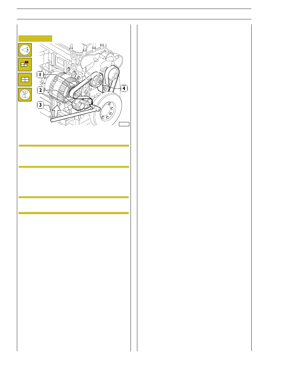
Figure 8
107903
Visually check that belt (1) is not worn out or broken; change
it as described below, if required.
In order to remove and refit belt (1), operate using a specific
tool (3) on belt tensioner (2) in direction shown by arrow.
Belt tensioner is
automatic and requires no
adjustment.
NOTE
NOTE To access the engine belt, it is necessary to remove
the protection guard, unscrewing the screws.
Check of water pump/alternator control belt condition
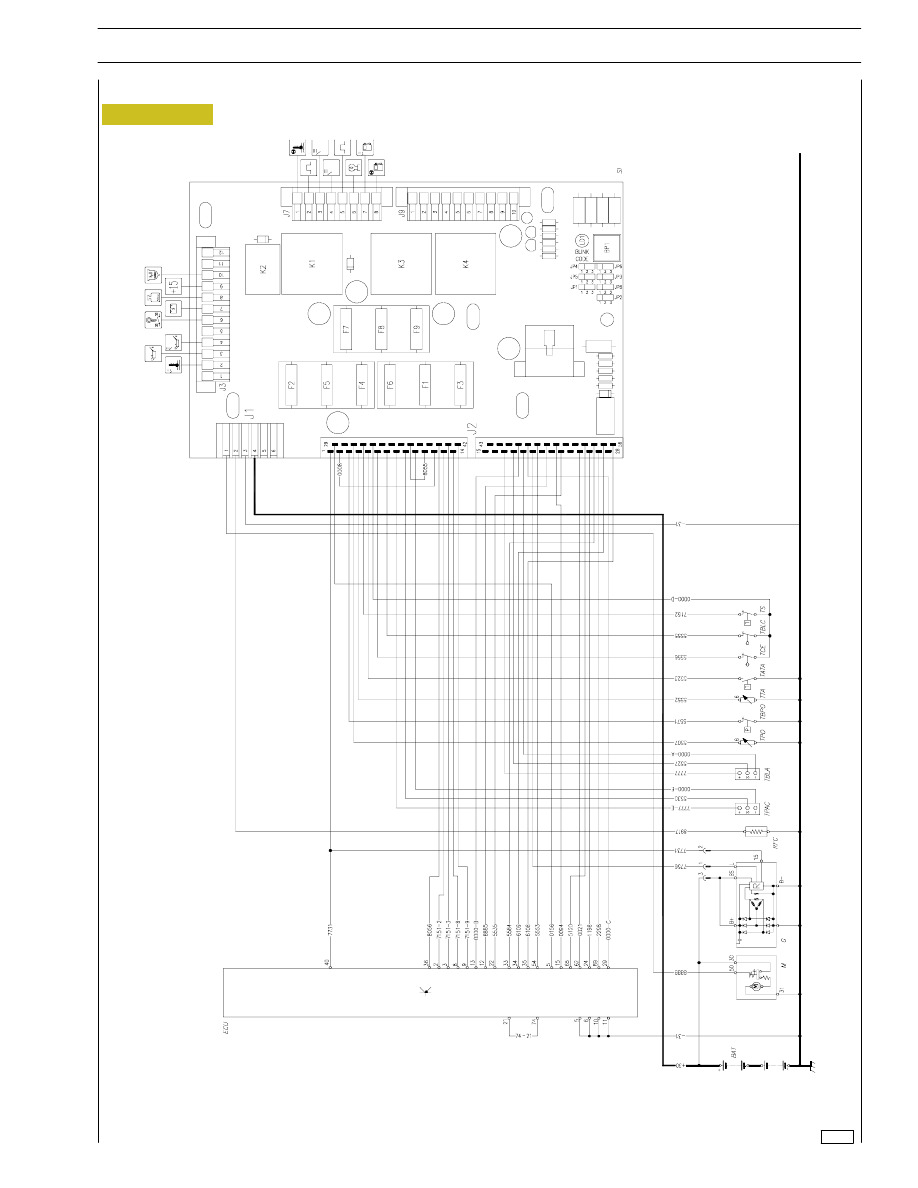
Figure 9
PRINCIPLE ELECTRICAL DIAGRAM
119624
23
CURSOR ENGINES G-DRIVE
SECTION 2 - G-DRIVE APPLICATION
Base - June 2007
24
SECTION 2 - G-DRIVE APPLICATION
CURSOR ENGINES G-DRIVE
Base - June 2007
BAT
Starter battery 12V
M
Starter motor
G
Battery charger alternator
RFC
Fuel filter heating resistor
TRFC
Fuel filter heating thermostat
TPAC
Water in the fuel filter transmitter
TBLA
Low engine water level transmitter
TPO
Engine oil pressure switch
TBPO
Low engine oil level pressure switch
TTA
Engine water temperature transmitter
TCE
No fuel transmitter (option)
TBLC
Float for fuel level
TS
Engine water heater thermostat
EDC
Engine electronic control unit
TATA
High engine water temperature thermostat
SI
Control panel - engine interface box
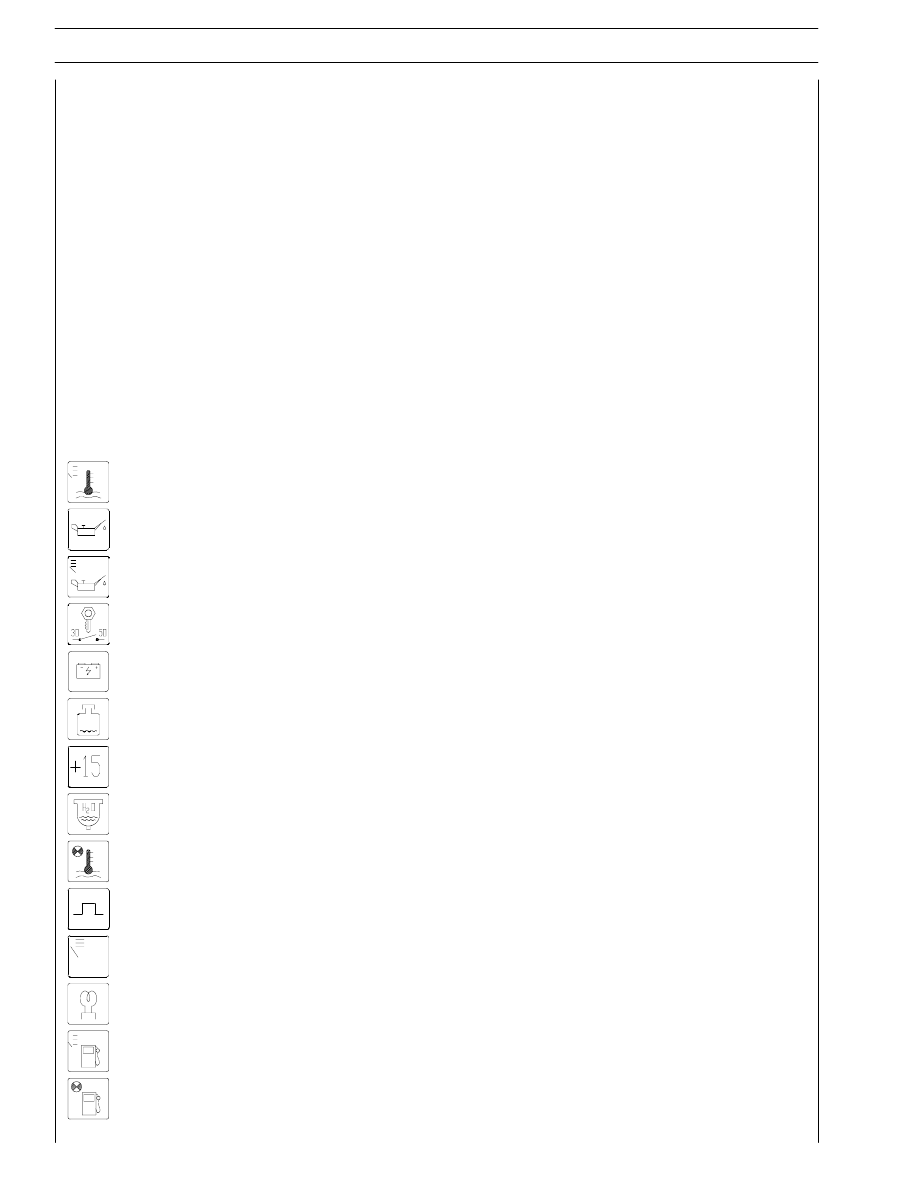
Function symbols for the control panel
ENGINE WATER TEMPERATURE THERMOMETER
LOW ENGINE OIL PRESSURE VISUAL WARNING
ENGINE OIL PRESSURE GAUGE
STARTING THE ENGINE (+50)
NO BATTERY CHARGING VISUAL WARNING
LOW ENGINE WATER LEVEL VISUAL WARNING
CAPTIVE KEY POSITIVE (+15)
WATER IN THE FUEL FILTER VISUAL WARNING
HIGH ENGINE WATER TEMPERATURE VISUAL WARNING
CAN LINE
CONTROL PANEL POWER SUPPLY
ENGINE PRE-HEATING
FUEL LEVEL VISUAL WARNING
NO FUEL VISUAL WARNING (OPTION)
Нет комментариевНе стесняйтесь поделиться с нами вашим ценным мнением.
Текст