Engines Iveco C87 / Cursor 87. Manual — part 15
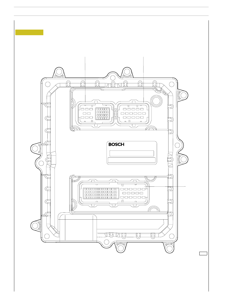
EDC 7 UC31 electronic control unit
Figure 4
A. Electro-injector connector - B. Chassis connector - C. Sensor connector
102373
A
C
B
32
SECTION 3 - INDUSTRIAL APPLICATION
F2C CURSOR ENGINES
Base - June 2006
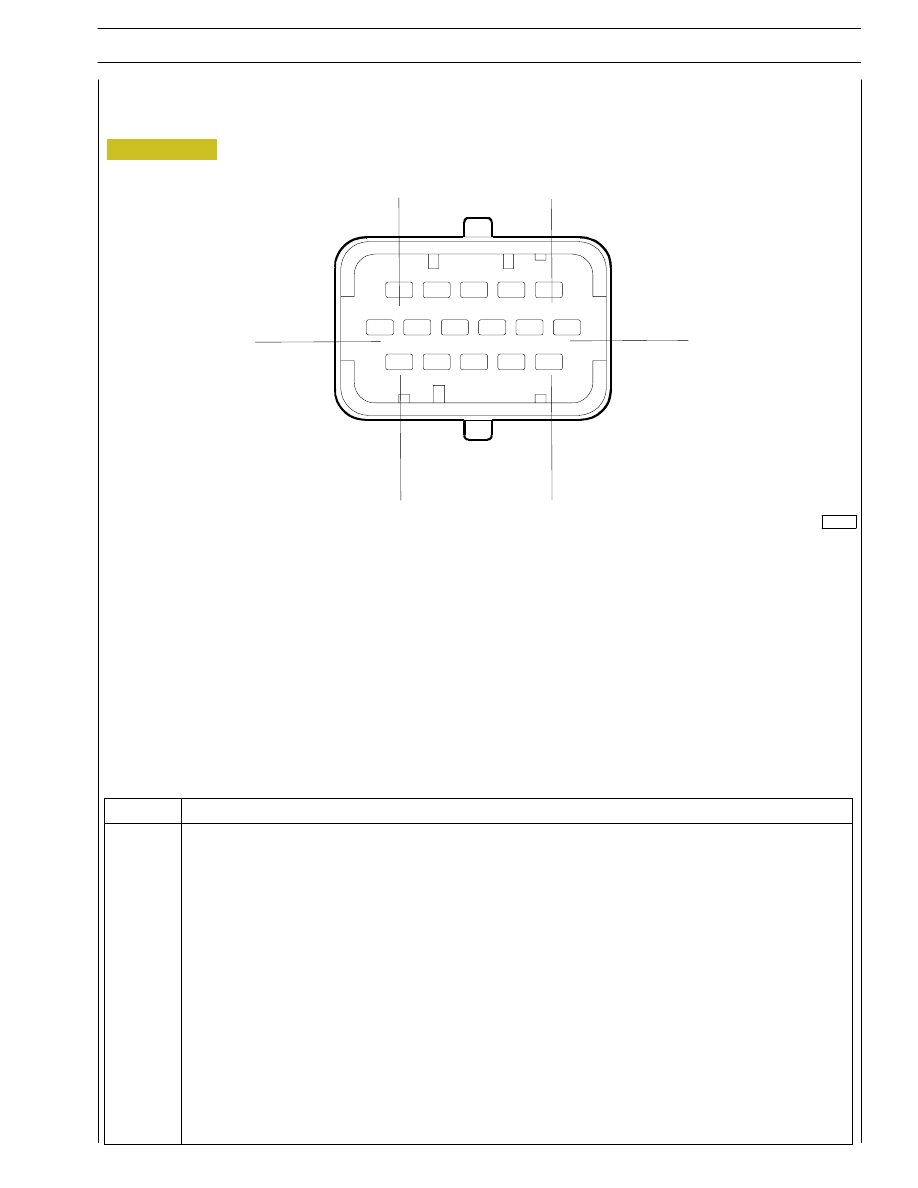
EDC control unit PIN-OUT
Electric injector connector ”A”
102374
Figure 5
16
12
6
1
5
11
Colour legend
B
black
R
red
U
blue
W
white
P
purple
G
green
N
brown
Y
yellow
O
orange
E
grey
K
pink
SECTION 3 - INDUSTRIAL APPLICATION
33
F2C CURSOR ENGINES
Pin
Function
1
Solenoid valve for electronic cylinder 5 injection
2
Solenoid valve for electronic cylinder 6 injection
3
Solenoid valve for electronic cylinder 4 injection
4
Solenoid valve for electronic cylinder 1 injection
5
Solenoid valve for electronic cylinder 3 injection
6
Solenoid valve for electronic cylinder 2 injection
7
-
8
-
9
-
10
-
11
Solenoid valve for electronic cylinder 2 injection
12
Solenoid valve for electronic cylinder 3 injection
13
Solenoid valve for electronic cylinder 1 injection
14
Solenoid valve for electronic cylinder 4 injection
15
Solenoid valve for electronic cylinder 6 injection
16
Solenoid valve for electronic cylinder 5 injection
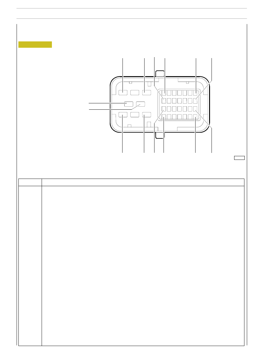
EDC control unit PIN-OUT
Sensor connector ”C”
Colour legend
B
black
R
red
U
blue
W
white
P
purple
G
green
N
brown
Y
yellow
O
orange
E
grey
K
pink
102375
Figure 6
6
8
16
9
15
22
36
29
30
23
3
1
4
5
34
SECTION 3 - INDUSTRIAL APPLICATION
F2C CURSOR ENGINES
Base - June 2006
Function
1
÷8
-
9
Engine speed sensor (timing)
10
Engine speed sensor (timing)
11
-
12
Pressure sensor on rail
13
Pressure sensor on rail
14
Pressure sensor on rail
15
Coolant temperature sensor
16
-
17
-
18
Fuel temperature sensor
19
Engine speed sensor (flywheel)
20
-
21
-
22
-
23
Engine speed sensor (flywheel)
24
Engine oil pressure/temperature sensor
25
Air pressure/temperature sensor supply
26
Coolant temperature sensor
27
Engine oil temperature/pressure sensor
28
Engine oil temperature/pressure sensor
29
-
30
-
31
-
32
Engine oil temperature/pressure sensor
33
Air pressure signal from air pressure/temperature sensor
34
Air temperature signal from air pressure/temperature sensor
35
Fuel temperature sensor
36
Air temperature signal from air pressure/temperature sensor
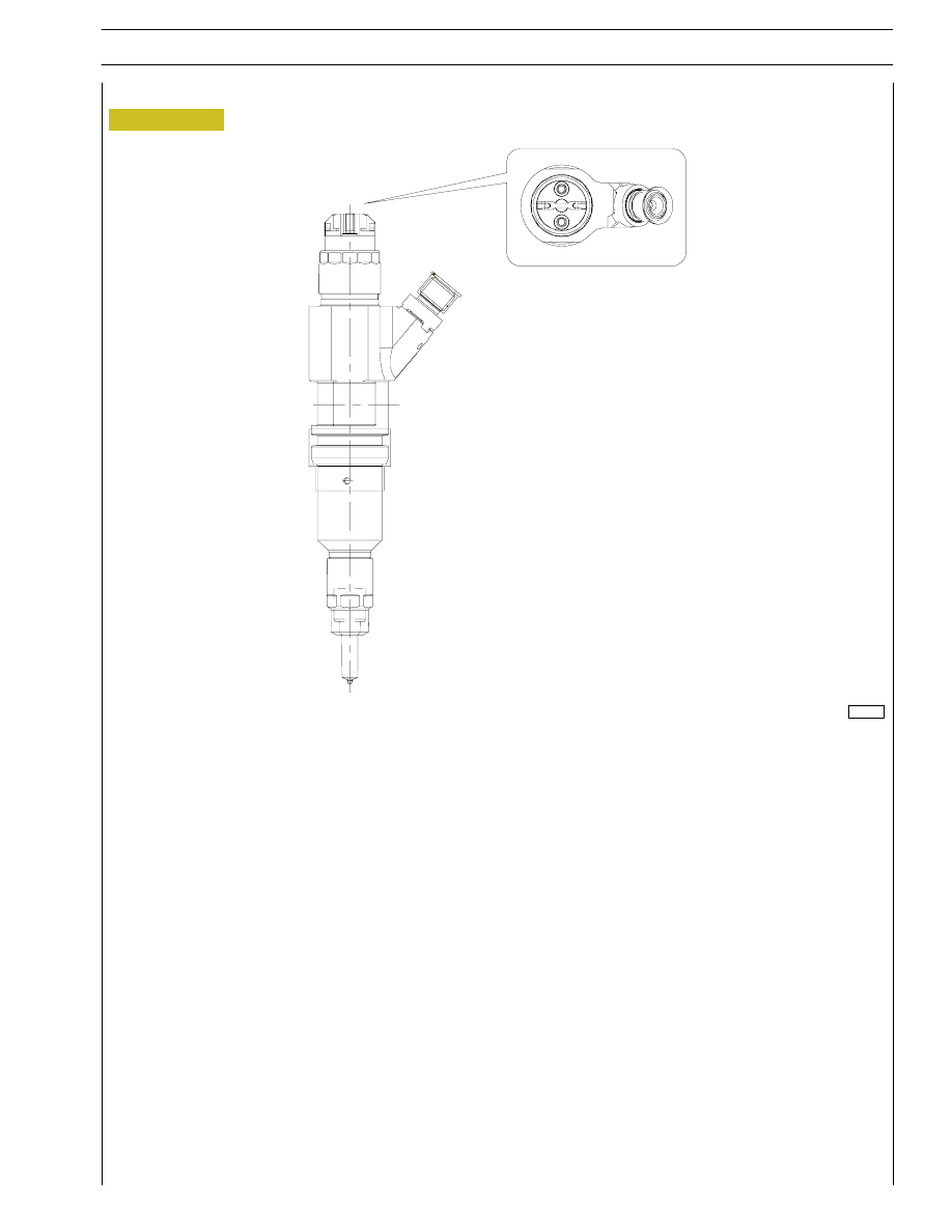
Figure 7
It is a N.O. solenoid valve.
They are connected to the EDC ECU on connector A.
The resistance of each injector coil is 0.56 - 0.57 Ohm.
The electroinjector can be considered as consisting of 2 parts:
- actuator - atomizer including pressure rod, needle and nozzle;
- control solenoid valve including coil and pilot valve.
The solenoid valve controls atomizer needle lift.
INJECTION START
When coil is energized, lock pin moves upward.
The control volume fuel flows to return duct causing control volume pressure drop.
At the same time, fuel pressure in pressure chamber causes needle uplift and therefore fuel injection in cylinder.
END OF INJECTION
When coil is de-energized, lock pin returns to lock position to look for a force balance such to return to needle close position and
stop injection.
Electroinjectors
114255
SECTION 3 - INDUSTRIAL APPLICATION
35
F2C CURSOR ENGINES
Нет комментариевНе стесняйтесь поделиться с нами вашим ценным мнением.
Текст