Engines Iveco N45, N67. Manual — part 18
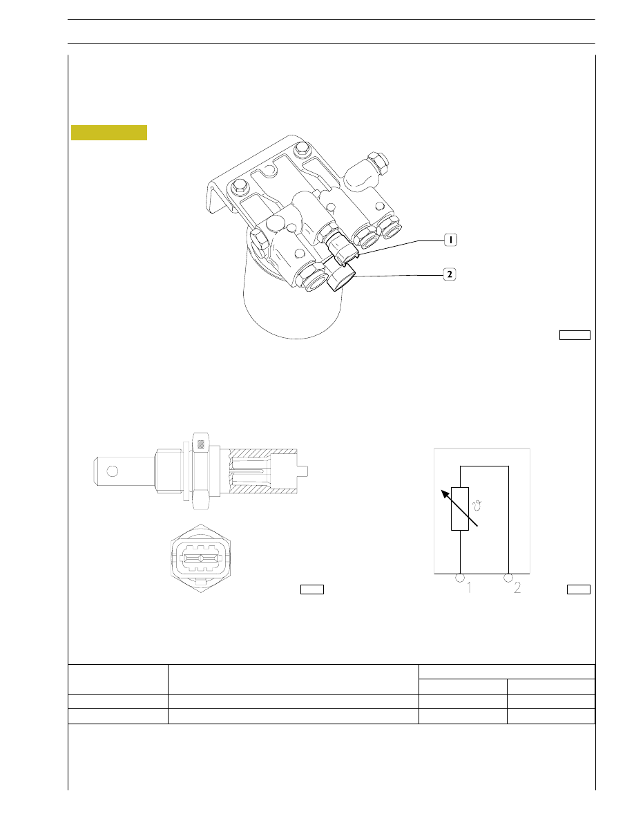
Fuel temperature sensor
This sensor is identical to the coolant temperature sensor.
This sensor detects the fuel temperature to provide the control unit with a parameter defining the thermal status of the fuel.
The fuel temperature sensor is connected to the control unit on pins 35C -18C.
The sensor impedance at 20
°C is approximately 2.50 Ω.
Figure 108
1. Fuel temperature sensor - 2. Filter heating resistance.
0051140t
The ECU drives the filter heater contactor at fuel temperature
≤ 5 °C.
107798
107799
Connector
SECTION 3 - DUTY-INDUSTRIAL APPLICATION
43
F4HE NEF ENGINES
Print P2D32N003GB
Base - February 2006
Ref
Description
ECU Pin
Ref.
Description
Coolant
Fuel
1
Ground
15C
35C
2
Temperature signal
26C
18C
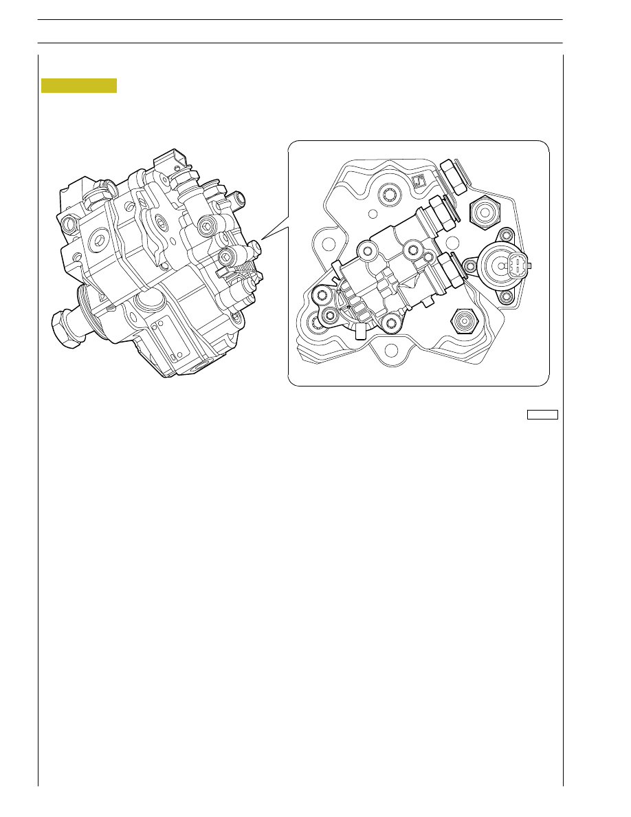
High pressure pump - pressure regulator
Figure 109
A. Pressure regulator.
000912t
The quantity of fuel supplied to the high pressure pump is metered by the pressure regulator on the low pressure system; the
pressure regulator is managed by the EDC7 control unit.
Delivery pressure to the rail is modulated between 250 and 1450 bar by the electronic control unit by controlling the pressure
regulator solenoid valve.
- This component is a N.O. solenoid valve.
- The solenoid is connected to the control unit on pins 9A - 10A.
- The solenoid valve impedance is approximately 3.2
Ω.
44
SECTION 3 - DUTY-INDUSTRIAL APPLICATION
F4HE NEF ENGINES
Base - February 2006
Print P2D32N00GB
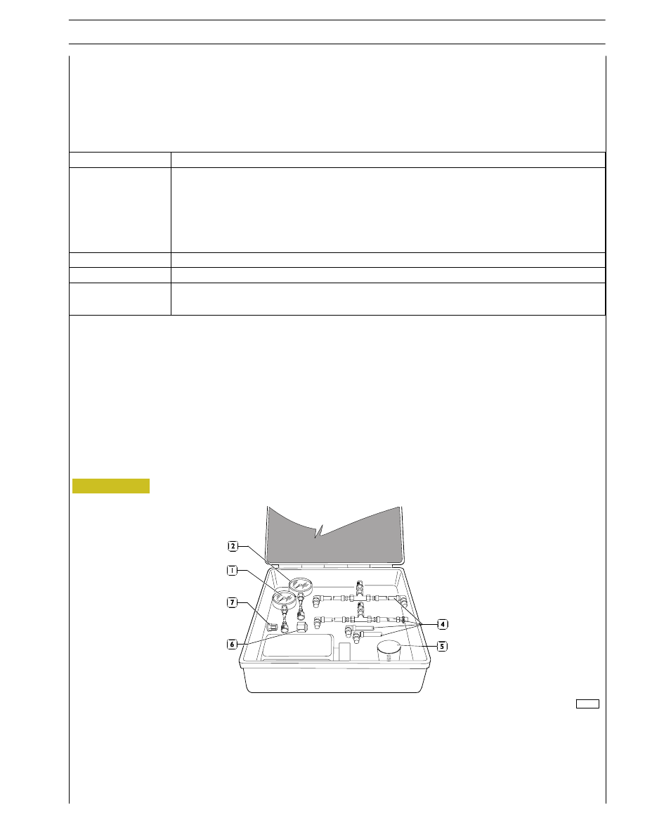
Figure 110
TESTS
CHECKING THE FUEL SYSTEM
This section analyses the tests for correctly troubleshooting and checking the fuel circuit and the common rail injection system.
The stated procedure can be used in the event of trouble with the engine injection system correlated with error codes 8.x saved
in the control unit, or not accompanied by any error code and the user notices a drop in performance. The following table gives
descriptions of error codes 8.x.
108599
DESCRIPTION OF TESTS AND CHECKS THAT CAN BE PERFORMED
The contemplated tests are:
- Low pressure supply test
- Test on the pressure relief valve on the rail
- Test on fuel backflow from the injector return
Necessary equipment
Use the kit dwg. 99305453 described in the figure.
1. Pressure gauge 1 (0 - 15bar) and standard couplings - 2. Pressure gauge 2 and standard couplings - 3. 2-litre container -
4. Pressure gauge pipes - 5. Graduated container of 100ml - 6. Plug for rail - 7. Closed Voss coupling.
SECTION 3 - DUTY-INDUSTRIAL APPLICATION
47
F4HE NEF ENGINES
Print P2D32N003GB
Base - February 2006
Error
Description
8.1
- Negative deviation of the fuel pressure (actual pressure higher than the objective pressure).
- Positive deviation of the fuel pressure (actual pressure lower than the objective pressure).
- Drop in fuel pressure with vehicle in motion (lack of diesel).
- Drop in fuel pressure with vehicle in motion: downhill with throttle pedal released (lack of diesel).
- Drop in fuel pressure with the engine idling (lack of diesel).
8.2
- Fuel pressure sensor on rail.
8.4
- Backflow valve control (opening the pressure relief valve DBV).
8.5
- Fuel pressure in the rail too high.
- Fuel pressure in the rail too low.
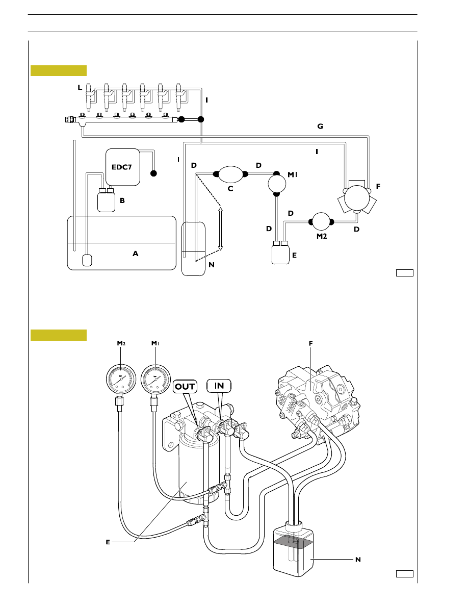
Figure 111
Low pressure supply test
The figure shows the diagram for using the components available in the kit dwg. 99305453.
108600
A. Fuel tank - B. Prefilter - C. Low-pressure pump - D. Fuel delivery circuit -
E. Fuel filter - F. High-pressure pump CP3 - G. High-pressure circuit - H. Common rail -
I. Fuel recirculation circuit - L. Injectors - M1. Pressure gauge 1 fuel filter inlet -
M2. Pressure gauge 2 fuel filter outlet - N. External container.
Figure 112
108601
48
SECTION 3 - DUTY-INDUSTRIAL APPLICATION
F4HE NEF ENGINES
Base - February 2006
Print P2D32N00GB
Нет комментариевНе стесняйтесь поделиться с нами вашим ценным мнением.
Текст